

JLR-10 Instruction Manual.pdf - Echomaster Marine Ltd.
JLR-10 Instruction Manual.pdf - Echomaster Marine Ltd.
JLR-10 Instruction Manual.pdf - Echomaster Marine Ltd.

Create successful ePaper yourself
Turn your PDF publications into a flip-book with our unique Google optimized e-Paper software.
<strong>JLR</strong>-<strong>10</strong> GPS Compass<br />
4.5.4 CDI Display Mode<br />
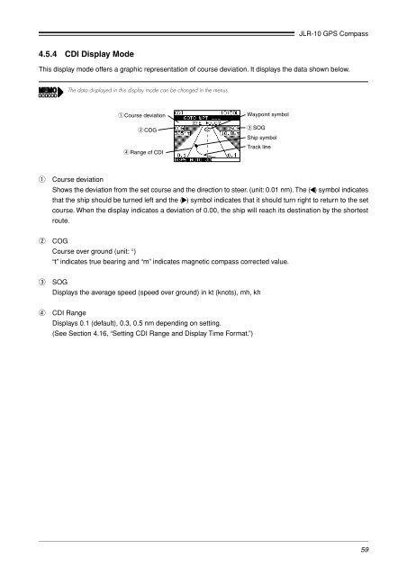
This display mode offers a graphic representation of course deviation. It displays the data shown below.<br />
The data displayed in this display mode can be changed in the menus.<br />
q Course deviation<br />
w COG<br />
r Range of CDI<br />
Waypoint symbol<br />
e SOG<br />
Ship symbol<br />
Track line<br />
q<br />
Course deviation<br />
Shows the deviation from the set course and the direction to steer. (unit: 0.01 nm). The ( ) symbol indicates<br />
that the ship should be turned left and the ( ) symbol indicates that it should turn right to return to the set<br />
course. When the display indicates a deviation of 0.00, the ship will reach its destination by the shortest<br />
route.<br />
w<br />
COG<br />
Course over ground (unit: °)<br />
“t” indicates true bearing and “m” indicates magnetic compass corrected value.<br />
e<br />
SOG<br />
Displays the average speed (speed over ground) in kt (knots), mh, kh<br />
r<br />
CDI Range<br />
Displays 0.1 (default), 0.3, 0.5 nm depending on setting.<br />
(See Section 4.16, “Setting CDI Range and Display Time Format.”)<br />
59


