

JLR-10 Instruction Manual.pdf - Echomaster Marine Ltd.
JLR-10 Instruction Manual.pdf - Echomaster Marine Ltd.
JLR-10 Instruction Manual.pdf - Echomaster Marine Ltd.

You also want an ePaper? Increase the reach of your titles
YUMPU automatically turns print PDFs into web optimized ePapers that Google loves.
<strong>JLR</strong>-<strong>10</strong> GPS Compass<br />
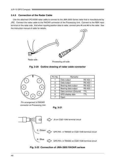
3.4.5 Connection of the Radar Cable<br />
Use the attached CFQ-6558 radar cable to connect to the JMA-3900 Series radar that is manufactured by<br />
JRC. Connect the radar cable to the RADAR connector of the Processing Unit. Connect to the NSK input<br />
terminal on the radar side. And when inputing position data to radar, connect pins #5 and #6 to the radar. See<br />
the instruction manual of radar for details.<br />
Radar side<br />
Processing unit side<br />
Fig. 3-20 Outline drawing of radar cable connector<br />
1 7<br />
2 6<br />
3 5<br />
4<br />
Pin arrangement of RADAR<br />
connector on Processing Unit<br />
Pin No.<br />
Remarks<br />
1 Data output RS-422 +<br />
2 Data output RS-422 –<br />
3 Bearing data output RS-422 +<br />
4 Bearing data output RS-422 –<br />
5 Data common (Ground) TTL<br />
6 GPS display data TTL<br />
7 Open<br />
Fig. 3-21<br />
J5 on CQD-1546 terminal circuit<br />
5 : Green<br />
GPS RX– in TB4302 on CQD-1546 terminal circuit<br />
6 : Blue<br />
GPS RX+ in TB4302 on CQD-1546 terminal circuit<br />
Fig. 3-22 Connection of JMA-3900 RADAR seriese<br />
40


