

JLR-10 Instruction Manual.pdf - Echomaster Marine Ltd.
JLR-10 Instruction Manual.pdf - Echomaster Marine Ltd.
JLR-10 Instruction Manual.pdf - Echomaster Marine Ltd.

You also want an ePaper? Increase the reach of your titles
YUMPU automatically turns print PDFs into web optimized ePapers that Google loves.
<strong>JLR</strong>-<strong>10</strong> GPS Compass<br />
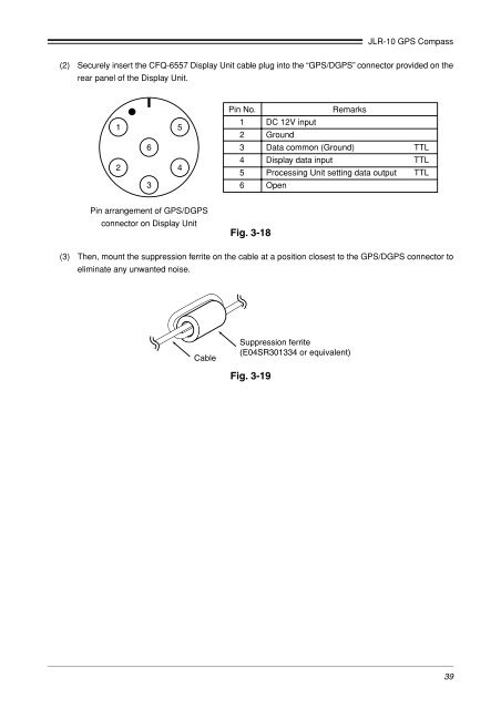
(2) Securely insert the CFQ-6557 Display Unit cable plug into the “GPS/DGPS” connector provided on the<br />
rear panel of the Display Unit.<br />
1 5<br />
6<br />
2<br />
4<br />
3<br />
Pin No.<br />
Remarks<br />
1 DC 12V input<br />
2 Ground<br />
3 Data common (Ground) TTL<br />
4 Display data input TTL<br />
5 Processing Unit setting data output TTL<br />
6 Open<br />
Pin arrangement of GPS/DGPS<br />
connector on Display Unit<br />
Fig. 3-18<br />
(3) Then, mount the suppression ferrite on the cable at a position closest to the GPS/DGPS connector to<br />
eliminate any unwanted noise.<br />
Cable<br />
Suppression ferrite<br />
(E04SR301334 or equivalent)<br />
Fig. 3-19<br />
39


