

JLR-10 Instruction Manual.pdf - Echomaster Marine Ltd.
JLR-10 Instruction Manual.pdf - Echomaster Marine Ltd.
JLR-10 Instruction Manual.pdf - Echomaster Marine Ltd.

Create successful ePaper yourself
Turn your PDF publications into a flip-book with our unique Google optimized e-Paper software.
<strong>JLR</strong>-<strong>10</strong> GPS Compass<br />
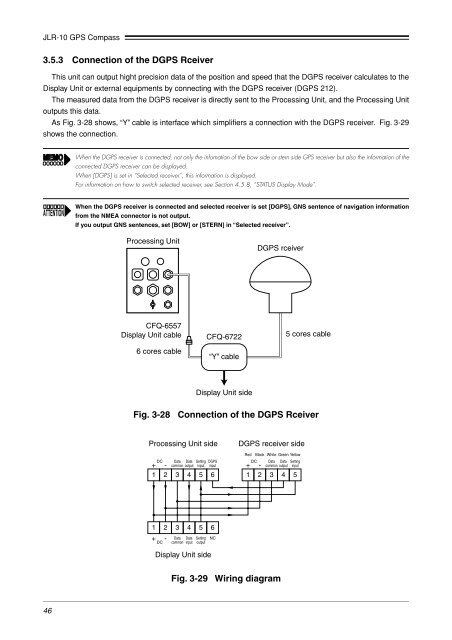
3.5.3 Connection of the DGPS Rceiver<br />
This unit can output hight precision data of the position and speed that the DGPS receiver calculates to the<br />
Display Unit or external equipments by connecting with the DGPS receiver (DGPS 212).<br />
The measured data from the DGPS receiver is directly sent to the Processing Unit, and the Processing Unit<br />
outputs this data.<br />
As Fig. 3-28 shows, “Y” cable is interface which simplifiers a connection with the DGPS receiver. Fig. 3-29<br />
shows the connection.<br />
When the DGPS receiver is connected, not only the infomation of the bow side or stern side GPS receiver but also the information of the<br />
connected DGPS receiver can be displayed.<br />
When [DGPS] is set in “Selected receiver”, this information is displayed.<br />
For information on how to switch selected receiver, see Section 4.5.8, “STATUS Display Mode”.<br />
When the DGPS receiver is connected and selected receiver is set [DGPS], GNS sentence of navigation information<br />
from the NMEA connector is not output.<br />
If you output GNS sentences, set [BOW] or [STERN] in “Selected receiver”.<br />
Processing Unit<br />
DGPS rceiver<br />
CFQ-6557<br />
Display Unit cable<br />
6 cores cable<br />
CFQ-6722<br />
“Y” cable<br />
5 cores cable<br />
Display Unit side<br />
Fig. 3-28 Connection of the DGPS Rceiver<br />
Processing Unit side<br />
Data<br />
Data<br />
- common output<br />
1 2 3 4 5 6<br />
+ DC<br />
Setting<br />
input<br />
DGPS<br />
input<br />
DGPS receiver side<br />
Red Black White Green Yellow<br />
DC Data Data Setting<br />
input<br />
+ - common output<br />
1 2 3 4 5<br />
1 2 3 4 5<br />
+ - Data Data Setting<br />
DC common input output<br />
6<br />
NC<br />
Display Unit side<br />
Fig. 3-29 Wiring diagram<br />
46


