

JLR-10 Instruction Manual.pdf - Echomaster Marine Ltd.
JLR-10 Instruction Manual.pdf - Echomaster Marine Ltd.
JLR-10 Instruction Manual.pdf - Echomaster Marine Ltd.

Create successful ePaper yourself
Turn your PDF publications into a flip-book with our unique Google optimized e-Paper software.
<strong>JLR</strong>-<strong>10</strong> GPS Compass<br />
3.5 Connection of the Optional Equipment<br />
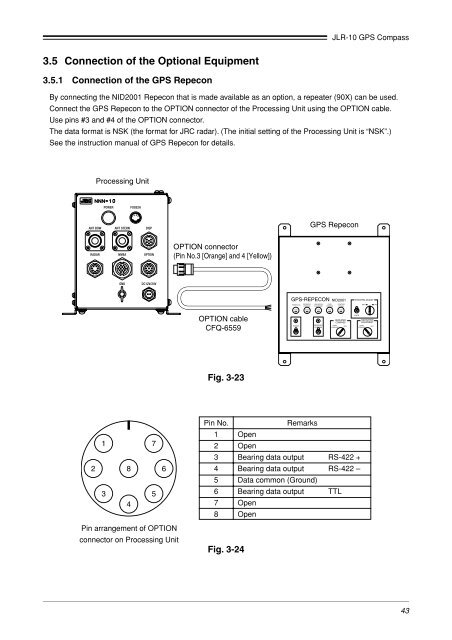
3.5.1 Connection of the GPS Repecon<br />
By connecting the NID2001 Repecon that is made available as an option, a repeater (90X) can be used.<br />
Connect the GPS Repecon to the OPTION connector of the Processing Unit using the OPTION cable.<br />
Use pins #3 and #4 of the OPTION connector.<br />
The data format is NSK (the format for JRC radar). (The initial setting of the Processing Unit is “NSK”.)<br />
See the instruction manual of GPS Repecon for details.<br />
Processing Unit<br />
POWER<br />
FUSE2A<br />
ANT BOW ANT STERN DISP<br />
GPS Repecon<br />
RADAR NMEA OPTION<br />
OPTION connector<br />
(Pin No.3 [Orange] and 4 [Yellow])<br />
GND<br />
DC12V/24V<br />
GPS-REPECON<br />
NID2001<br />
POWER (3A)<br />
REPEATER NAVIGATION GYRO SYNCHRO<br />
COMPASS EQUIPMENT COMPASS SYGNAL<br />
SYNCHRO ADJUST<br />
DEC.<br />
INC.<br />
OPTION cable<br />
CFQ-6559<br />
FUSE FUSE FUSE FUSE FUSE<br />
POWER<br />
REPEARER<br />
COMPASS<br />
REPEATER<br />
COMPASS<br />
GYRO<br />
GPS<br />
COMPASS<br />
LOCK<br />
NAVIGATION<br />
EQUIPMENT<br />
GYRO<br />
COMPASS<br />
GPS<br />
Fig. 3-23<br />
1 7<br />
2 8 6<br />
3 5<br />
4<br />
Pin arrangement of OPTION<br />
connector on Processing Unit<br />
Pin No.<br />
Remarks<br />
1 Open<br />
2 Open<br />
3 Bearing data output RS-422 +<br />
4 Bearing data output RS-422 –<br />
5 Data common (Ground)<br />
6 Bearing data output TTL<br />
7 Open<br />
8 Open<br />
Fig. 3-24<br />
43


