

JLR-10 Instruction Manual.pdf - Echomaster Marine Ltd.
JLR-10 Instruction Manual.pdf - Echomaster Marine Ltd.
JLR-10 Instruction Manual.pdf - Echomaster Marine Ltd.

Create successful ePaper yourself
Turn your PDF publications into a flip-book with our unique Google optimized e-Paper software.
<strong>JLR</strong>-<strong>10</strong> GPS Compass<br />
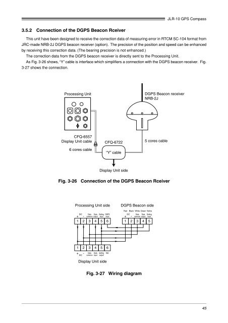
3.5.2 Connection of the DGPS Beacon Rceiver<br />
This unit have been designed to receive the correction data of measuring error in RTCM SC-<strong>10</strong>4 format from<br />
JRC-made NRB-2J DGPS beacon receiver (option). The precision of the position and speed can be enhanced<br />
by receiving this correction data. (The bearing precision is not enhanced.)<br />
The correction data from the DGPS beacon receiver is directly sent to the Processing Unit.<br />
As Fig. 3-26 shows, “Y” cable is interface which simplifiers a connection with the DGPS beacon receiver. Fig.<br />
3-27 shows the connection.<br />
Processing Unit<br />
DGPS Beacon receiver<br />
NRB-2J<br />
CFQ-6557<br />
Display Unit cable<br />
6 cores cable<br />
CFQ-6722<br />
“Y” cable<br />
5 cores cable<br />
Display Unit side<br />
Fig. 3-26 Connection of the DGPS Beacon Rceiver<br />
Processing Unit side<br />
Data<br />
Data<br />
- common output<br />
1 2 3 4 5 6<br />
+ DC<br />
Setting<br />
input<br />
DGPS<br />
input<br />
DGPS Beacon side<br />
Red Black White Green Yellow<br />
DC<br />
Data<br />
Data<br />
Setting<br />
input<br />
+ - common output<br />
1 2 3 4 5<br />
1 2 3 4 5<br />
+ - Data Data Setting<br />
DC common input output<br />
6<br />
NC<br />
Display Unit side<br />
Fig. 3-27 Wiring diagram<br />
45


