

272144 Vanguard Twin Cylinder OHV BRIGGS & STRATTON.pdf
272144 Vanguard Twin Cylinder OHV BRIGGS & STRATTON.pdf
272144 Vanguard Twin Cylinder OHV BRIGGS & STRATTON.pdf

Create successful ePaper yourself
Turn your PDF publications into a flip-book with our unique Google optimized e-Paper software.
Inspect Carburetor<br />
Inspect all parts for wear, cracks, nicks and burrs.<br />
Inspect float for leaks. Replace damaged parts.<br />
Assemble Carburetor<br />
When assembling carburetor, use new seals and<br />
gaskets.<br />
Install Fuel Inlet Seat and Body<br />
1. Install new inlet seat (3) with chamfered end<br />
down, Fig. 106.<br />
2. Press in new body (2) using Tool #19135 (1).<br />
<br />
<br />
<br />
8. Assemble spacer (9) onto choke shaft.<br />
9. Insert spring and check ball (11) in to spring<br />
pocket. Compress with a small round punch.<br />
10. Push choke shaft into hole until ball engages<br />
groove in choke shaft.<br />
11. Install retainer (12) to shaft.<br />
12. Install choke plate.<br />
NOTE: Use LOCTITE 222 on screw threads.<br />
<br />
<br />
Fig. 108<br />
<br />
<br />
<br />
13. Install fixed main jet (16) with Jet Screwdriver<br />
#19062 (18), Fig. 109.<br />
14. Install washer (15) and plug (14).<br />
Fig. 106<br />
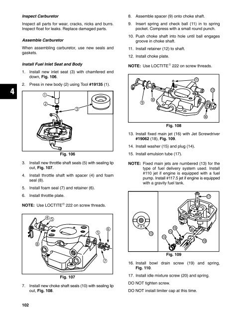
3. Install new throttle shaft seals (5) with sealing lip<br />
out, Fig. 107.<br />
4. Install throttle shaft with spacer (4) and foam<br />
seal (8).<br />
5. Install foam seal (7) and retainer (6).<br />
6. Install throttle plate.<br />
15. Install emulsion tube (17).<br />
NOTE: Fixed main jets are numbered (13) for the<br />
type of fuel delivery system used. Install<br />
#110 jet if engine is equipped with a fuel<br />
pump. Install #117.5 jet if engine is equipped<br />
with a gravity fuel tank.<br />
<br />
NOTE: Use LOCTITE ® 222 on screw threads.<br />
<br />
ÒÒ<br />
<br />
ÒÒ<br />
Ò Ò ÒÒ<br />
<br />
<br />
ÒÒ<br />
<br />
<br />
<br />
<br />
<br />
<br />
Fig. 107<br />
<br />
7. Install new choke shaft seals (10) with sealing lip<br />
out, Fig. 108.<br />
Fig. 109<br />
16. Install bowl drain screw (19) and spring,<br />
Fig. 110.<br />
17. Install idle mixture screw (20) and spring.<br />
DO NOT tighten screw.<br />
DO NOT install limiter cap at this time.<br />
ÒÒ Ò<br />
Ò<br />
102


