

272144 Vanguard Twin Cylinder OHV BRIGGS & STRATTON.pdf
272144 Vanguard Twin Cylinder OHV BRIGGS & STRATTON.pdf
272144 Vanguard Twin Cylinder OHV BRIGGS & STRATTON.pdf

You also want an ePaper? Increase the reach of your titles
YUMPU automatically turns print PDFs into web optimized ePapers that Google loves.
A jumper wire is required for this test.<br />
Make sure key switch is OFF before connecting<br />
jumper wire.<br />
NOTE: Mark or identify the charging indicator wire<br />
in the output harness before disconnecting<br />
the harness from the connector.<br />
CAUTION: If the jumper wire contacts the charging<br />
output wire during the test while the key switch<br />
is ON, the wiring harness could be damaged.<br />
1. Disconnect output harness (3) at WHITE connector<br />
(4), Fig. 44.<br />
2. Attach one end of jumper wire (5) to a good<br />
ground.<br />
3. Attach other end of jumper wire (6) to charge<br />
indicator terminal in harness connector, Fig. 44.<br />
a. Turn key switch to ON position (1).<br />
b. If bulb (2) LIGHTS, charge indicator wiring<br />
system is OK. Replace regulator/rectifier.<br />
c. If bulb DOES NOT LIGHT, replace bulb.<br />
d. If new bulb does not light, the problem is an<br />
OPEN CIRCUIT (broken wire) in the<br />
charging indicator circuit. Refer to typical<br />
wiring diagram.<br />
• SYMPTOM: Charge Indicator Light Stays ON –<br />
Engine Running.<br />
NOTE: Indicator light will remain ON if battery voltage<br />
is below 12 volts.<br />
4. Check indicator light wiring.<br />
a. If wiring is grounded, light will remain ON<br />
when engine is running.<br />
b. If wiring is OK, replace regulator/rectifier.<br />
<br />
<br />
<br />
<br />
<br />
Fig. 44<br />
<br />
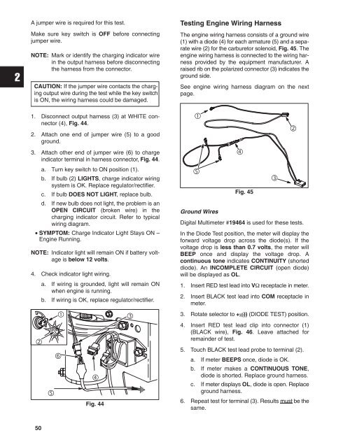
Testing Engine Wiring Harness<br />
The engine wiring harness consists of a ground wire<br />
(1) with a diode (4) for each armature (5) and a separate<br />
wire (2) for the carburetor solenoid, Fig. 45. The<br />
engine wiring harness is connected to the wiring harness<br />
provided by the equipment manufacturer. A<br />
raised rib on the polarized connector (3) indicates the<br />
ground side.<br />
See engine wiring harness diagram on the next<br />
page.<br />
<br />
<br />
Ground Wires<br />
<br />
Fig. 45<br />
<br />
<br />
Digital Multimeter #19464 is used for these tests.<br />
In the Diode Test position, the meter will display the<br />
forward voltage drop across the diode(s). If the<br />
voltage drop is less than 0.7 volts, the meter will<br />
BEEP once and display the voltage drop. A<br />
continuous tone indicates CONTINUITY (shorted<br />
diode). An INCOMPLETE CIRCUIT (open diode)<br />
will be displayed as OL.<br />
1. Insert RED test lead into V receptacle in meter.<br />
2. Insert BLACK test lead into COM receptacle in<br />
meter.<br />
3. Rotate selector to +))))) (DIODE TEST) position.<br />
4. Insert RED test lead clip into connector (1)<br />
(BLACK wire), Fig. 46. Leave attached for<br />
remainder of test.<br />
5. Touch BLACK test lead probe to terminal (2).<br />
a. If meter BEEPS once, diode is OK.<br />
b. If meter makes a CONTINUOUS TONE,<br />
diode is shorted. Replace ground harness.<br />
c. If meter displays OL, diode is open. Replace<br />
ground harness.<br />
6. Repeat test for terminal (3). Results must be the<br />
same.<br />
50


