

272144 Vanguard Twin Cylinder OHV BRIGGS & STRATTON.pdf
272144 Vanguard Twin Cylinder OHV BRIGGS & STRATTON.pdf
272144 Vanguard Twin Cylinder OHV BRIGGS & STRATTON.pdf

You also want an ePaper? Increase the reach of your titles
YUMPU automatically turns print PDFs into web optimized ePapers that Google loves.
2. Two BLACK leads (2) from stator.<br />
3. YELLOW connector (3) with two pin terminals.<br />
4. Two YELLOW leads (4) to regulator-rectifier.<br />
5. Regulator-rectifier (5).<br />
6. One RED lead from regulator-rectifier to RED<br />
connector output lead (6).<br />
• 20 Volts – 10 Amp System<br />
• 30 Volts – 16 Amp System<br />
6. If NO or LOW output is found check for bare<br />
wires or other defects. If wiring defects are not<br />
visible, replace the stator.<br />
Regulator-Rectifier Test<br />
<br />
<br />
NOTE: Make sure the regulator-rectifier is securely<br />
mounted to engine. Regulator-rectifier will<br />
not function unless it is grounded to engine.<br />
When testing regulator-rectifier for<br />
amperage output, a 12 volt battery with a<br />
minimum charge of 5 volts is required.<br />
There will be no output if battery voltage is<br />
below 5 volts.<br />
<br />
<br />
Fig. 26<br />
<br />
<br />
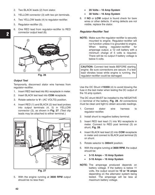
Output Test<br />
Temporarily, disconnect stator wire harness from<br />
regulator-rectifier.<br />
1. Insert RED test lead into V receptacle in meter.<br />
2. Insert BLACK test lead into COM receptacle.<br />
3. Rotate selector to V~ (AC VOLTS) position.<br />
4. Insert RED (1) and BLACK (2) test lead probes<br />
into output terminals (4, 5) in YELLOW<br />
connector (3), as shown in Fig. 27. (Test clip<br />
leads may be attached to either terminal.)<br />
CAUTION: Connect test leads BEFORE starting<br />
engine. Be sure connections are secure. If a test<br />
lead vibrates loose while engine is running, the<br />
regulator-rectifier could be damaged.<br />
Use the DC Shunt #19359 (4) to avoid blowing the<br />
fuse in the test meter when testing the DC output of<br />
the 16 amp system.<br />
The DC shunt MUST be installed to the NEGATIVE<br />
(-) terminal of the battery, Fig. 28. All connections<br />
must be clean and tight to obtain accurate readings.<br />
1. Connect stator wire harness to<br />
regulator-rectifier.<br />
2. Install shunt to negative battery terminal.<br />
3. Insert RED test lead (1) into V receptacle in<br />
meter. Connect to RED post terminal (3) on<br />
shunt, Fig. 28.<br />
<br />
4. Insert BLACK test lead (2) into COM receptacle<br />
in meter and connect to BLACK post terminal (5)<br />
on shunt.<br />
ÌÌ<br />
5. Rotate selector to 300mV position.<br />
<br />
Fig. 27<br />
<br />
<br />
<br />
5. With the engine running at 3600 RPM output<br />
should be no less than:<br />
6. With the engine running at 3600 RPM, the output<br />
should be:<br />
• 3-10 Amps – 10 Amp System<br />
• 3-16 Amps – 16 Amp System<br />
NOTE: The amperage produced depends on<br />
battery voltage. If the battery is below 11<br />
volts, the output would be 10 or 16 amps<br />
depending on the alternator system being<br />
tested. The amperage will be less at<br />
maximum battery voltage.<br />
42


