

272144 Vanguard Twin Cylinder OHV BRIGGS & STRATTON.pdf
272144 Vanguard Twin Cylinder OHV BRIGGS & STRATTON.pdf
272144 Vanguard Twin Cylinder OHV BRIGGS & STRATTON.pdf

You also want an ePaper? Increase the reach of your titles
YUMPU automatically turns print PDFs into web optimized ePapers that Google loves.
POWERLINK SYSTEM<br />
Some V-<strong>Twin</strong> engines are equipped with the Power-<br />
LinkSystem, an on-board generator system for<br />
riding tractors that provides 120 volt, 60 cycle AC to<br />
a GFCI receptacle provided by the OEM.<br />
The PowerLink system will not function unless the<br />
parking brake on the tractor is ENGAGED (1), Fig.<br />
52, and the PTO on the tractor is OFF. The Power-<br />
Link system will shut down if there is a system or<br />
temperature overload, or if there is a ground fault.<br />
4. If the power goes OFF the GFCI is working<br />
correctly. Press the reset button to restore power.<br />
NOTE: Use only OEM approved GFCI<br />
components.<br />
<br />
Resetting PowerLink System<br />
NOTE: Turn OFF or unplug any device or appliance<br />
that was connected to the PowerLink<br />
System. Verify that the reset button on the<br />
GFCI has not been tripped.<br />
1. The engine must be running with the parking<br />
brake set and the PTO DISENGAGED.<br />
2. Actuate the PowerLink reset switch. Move the<br />
reset switch to the OFF position, then return it to<br />
the ON position. For operator safety there is a<br />
two second delay in power to the GFCI<br />
receptacle after reset.<br />
Testing the GFCI<br />
Fig. 33<br />
<br />
1. The engine must be running with the parking<br />
brake (1) set and the PTO DISENGAGED.<br />
2. Plug in a trouble light or radio to confirm that<br />
electrical power is present.<br />
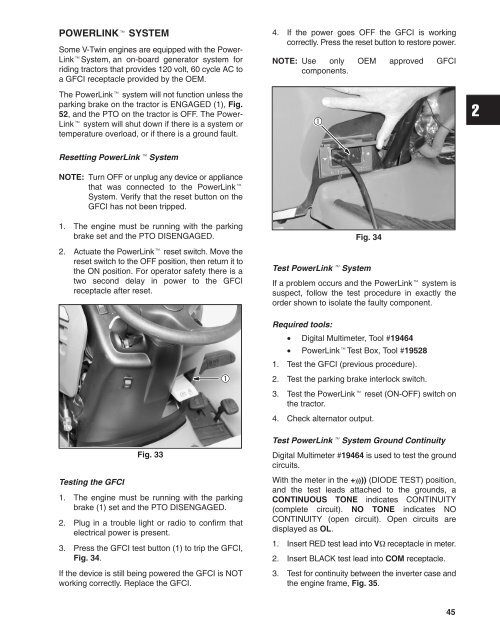
3. Press the GFCI test button (1) to trip the GFCI,<br />
Fig. 34.<br />
If the device is still being powered the GFCI is NOT<br />
working correctly. Replace the GFCI.<br />
Fig. 34<br />
Test PowerLink System<br />
If a problem occurs and the PowerLink system is<br />
suspect, follow the test procedure in exactly the<br />
order shown to isolate the faulty component.<br />
Required tools:<br />
• Digital Multimeter, Tool #19464<br />
• PowerLinkTest Box, Tool #19528<br />
1. Test the GFCI (previous procedure).<br />
2. Test the parking brake interlock switch.<br />
3. Test the PowerLink reset (ON-OFF) switch on<br />
the tractor.<br />
4. Check alternator output.<br />
Test PowerLink System Ground Continuity<br />
Digital Multimeter #19464 is used to test the ground<br />
circuits.<br />
With the meter in the +))))) (DIODE TEST) position,<br />
and the test leads attached to the grounds, a<br />
CONTINUOUS TONE indicates CONTINUITY<br />
(complete circuit). NO TONE indicates NO<br />
CONTINUITY (open circuit). Open circuits are<br />
displayed as OL.<br />
1. Insert RED test lead into V receptacle in meter.<br />
2. Insert BLACK test lead into COM receptacle.<br />
3. Test for continuity between the inverter case and<br />
the engine frame, Fig. 35.<br />
45


