

272144 Vanguard Twin Cylinder OHV BRIGGS & STRATTON.pdf
272144 Vanguard Twin Cylinder OHV BRIGGS & STRATTON.pdf
272144 Vanguard Twin Cylinder OHV BRIGGS & STRATTON.pdf

You also want an ePaper? Increase the reach of your titles
YUMPU automatically turns print PDFs into web optimized ePapers that Google loves.
Assemble<br />
1. Assemble clutch drive (5) to starter shaft. Rotate<br />
clutch until it drops into place, Fig. 11.<br />
2. Install pinion gear (4) with beveled side of teeth<br />
UP.<br />
3. Install washer (3) and retainer (1).<br />
4. Install NEW roll pin (2).<br />
NOTE: Slot in roll pin should face up.<br />
<br />
Fig. 11<br />
<br />
<br />
<br />
<br />
3. Assemble lower spring retainer with OPEN END<br />
UP.<br />
4. Install spring.<br />
5. Install upper spring retainer with OPEN END UP.<br />
6. Compress spring. Install NEW retaining ring to<br />
shaft.<br />
7. Compress retaining ring with pliers to ensure<br />
that it is seated properly in groove in shaft.<br />
8. Pull up on upper spring retainer until retaining<br />
ring snaps into groove in upper spring retainer.<br />
9. Push dust cover down until it snaps into groove<br />
in lower spring retainer.<br />
<br />
<br />
<br />
<br />
<br />
<br />
<br />
Steel Pinion Style<br />
<br />
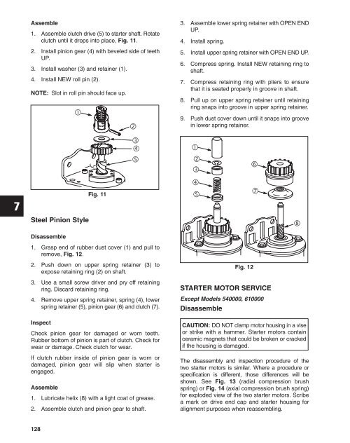
Disassemble<br />
1. Grasp end of rubber dust cover (1) and pull to<br />
remove, Fig. 12.<br />
2. Push down on upper spring retainer (3) to<br />
expose retaining ring (2) on shaft.<br />
3. Use a small screw driver and pry off retaining<br />
ring. Discard retaining ring.<br />
4. Remove upper spring retainer, spring (4), lower<br />
spring retainer (5), pinion gear (6) and clutch (7).<br />
Inspect<br />
Check pinion gear for damaged or worn teeth.<br />
Rubber bottom of pinion is part of clutch. Check for<br />
wear or damage. Check clutch for wear.<br />
If clutch rubber inside of pinion gear is worn or<br />
damaged, pinion gear will slip when starter is<br />
engaged.<br />
Assemble<br />
1. Lubricate helix (8) with a light coat of grease.<br />
2. Assemble clutch and pinion gear to shaft.<br />
Fig. 12<br />
STARTER MOTOR SERVICE<br />
Except Models 540000, 610000<br />
Disassemble<br />
CAUTION: DO NOT clamp motor housing in a vise<br />
or strike with a hammer. Starter motors contain<br />
ceramic magnets that could be broken or cracked<br />
if the housing is damaged.<br />
The disassembly and inspection procedure of the<br />
two starter motors is similar. Where a procedure or<br />
specification is different, those differences will be<br />
shown. See Fig. 13 (radial compression brush<br />
spring) or Fig. 14 (axial compression brush spring)<br />
for exploded view of the two starter motors. Scribe<br />
a mark on drive end cap and starter housing for<br />
alignment purposes when reassembling.<br />
128


