

272144 Vanguard Twin Cylinder OHV BRIGGS & STRATTON.pdf
272144 Vanguard Twin Cylinder OHV BRIGGS & STRATTON.pdf
272144 Vanguard Twin Cylinder OHV BRIGGS & STRATTON.pdf

Create successful ePaper yourself
Turn your PDF publications into a flip-book with our unique Google optimized e-Paper software.
GENERAL INFORMATION<br />
Install new piston rings whenever the engine is<br />
disassembled for major servicing or overhaul,<br />
providing that cylinder bores are within specification.<br />
<br />
1. Remove any carbon or ridge at the top of the<br />
cylinder bore. This will prevent breaking the<br />
rings when removing the piston and connecting<br />
rod from the engine.<br />
2. Remove the connecting rod cap. Push the<br />
piston and connecting rod out through the top of<br />
the cylinder.<br />
3. Measure cylinder bores before checking pistons<br />
and rings. If cylinder bores require re-sizing it is<br />
not necessary to check pistons and rings, since<br />
a new oversized piston assembly will be used.<br />
Resize a cylinder bore if it is more than 0.003” (0.08<br />
mm) oversize, or 0.0015” (0.04 mm) out of round.<br />
Disassemble<br />
1. Remove piston rings using Ring Expander<br />
#19340 (1), Fig. 1.<br />
2. Remove oil control ring coil expander and oil<br />
control rings.<br />
<br />
Fig. 2<br />
Inspect Piston and Piston Rings<br />
NOTE: If the cylinder is not going to be resized and<br />
the piston shows no signs of scoring, the<br />
piston should be checked.<br />
1. Check side clearance of ring grooves using a<br />
feeler gauge and NEW piston rings (3), Fig. 3.<br />
Replace the piston if the ring groove is worn<br />
beyond specification.<br />
Side Clearance Reject Dimension:<br />
All Except Models 540000, 610000<br />
• Compression Rings – 0.004” (0.10 mm)<br />
• Oil Rings – 0.008” (0.20 mm)<br />
Models 540000, 610000<br />
• Top Compression Ring – 0.009” (0.23 mm)<br />
• Center Compression Ring – 0.006” (0.15 mm)<br />
• Oil Rings – 0.004” (0.10 mm)<br />
Fig. 1<br />
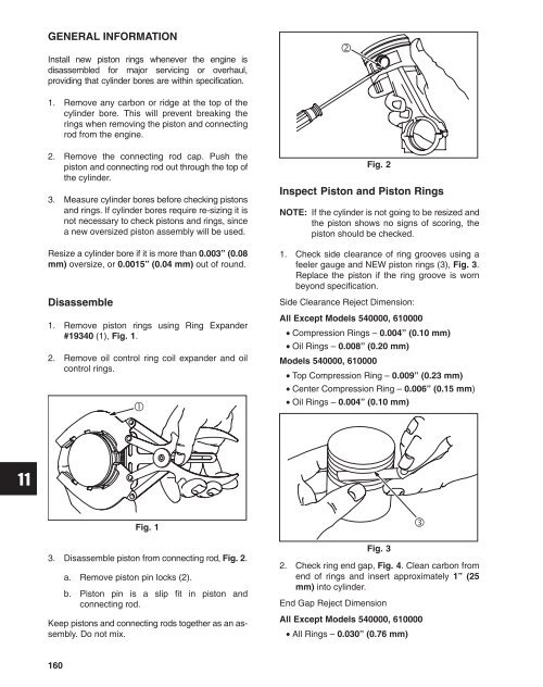
3. Disassemble piston from connecting rod, Fig. 2.<br />
a. Remove piston pin locks (2).<br />
b. Piston pin is a slip fit in piston and<br />
connecting rod.<br />
Keep pistons and connecting rods together as an assembly.<br />
Do not mix.<br />
Fig. 3<br />
<br />
2. Check ring end gap, Fig. 4. Clean carbon from<br />
end of rings and insert approximately 1” (25<br />
mm) into cylinder.<br />
End Gap Reject Dimension<br />
All Except Models 540000, 610000<br />
• All Rings – 0.030” (0.76 mm)<br />
160


