

272144 Vanguard Twin Cylinder OHV BRIGGS & STRATTON.pdf
272144 Vanguard Twin Cylinder OHV BRIGGS & STRATTON.pdf
272144 Vanguard Twin Cylinder OHV BRIGGS & STRATTON.pdf

You also want an ePaper? Increase the reach of your titles
YUMPU automatically turns print PDFs into web optimized ePapers that Google loves.
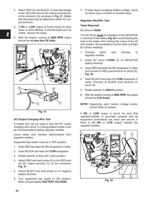
4. Attach RED (2) and BLACK (1) test lead probes<br />
to the YELLOW wire (4) AC output terminals (6),<br />
of the connector (3), as shown in Fig. 31. (Meter<br />
test clip leads may be attached to either AC output<br />
terminal.)<br />
5. If NO or LOW output is found check for bare<br />
wires or other defects. If shorted leads are not<br />
visible, replace the stator.<br />
6. With the engine running at 3600 RPM output<br />
should be no less than 26 Volts.<br />
<br />
<br />
<br />
<br />
<br />
Fig. 31<br />
<br />
<br />
DC Output Charging Wire Test<br />
A simple test can be used to test the DC output<br />
charging wire circuit. If a wiring problem exists it can<br />
be corrected before testing regulator-rectifier.<br />
Leave stator wire harness disconnected from<br />
regulator-rectifier.<br />
Equipment key switch must be in OFF position.<br />
1. Insert RED test lead into V receptacle in meter.<br />
2. Insert BLACK test lead into COM receptacle.<br />
3. Rotate selector to V== (DC volts) position.<br />
4. Attach RED test lead probe (2) to the RED wire<br />
(5) DC output terminal (7), of the connector,<br />
Fig. 31.<br />
5. Attach BLACK test lead probe (1) to negative<br />
battery terminal.<br />
6. Turn equipment key switch to ON position.<br />
Meter should display BATTERY VOLTAGE.<br />
7. If meter does not display battery voltage, check<br />
for blown fuse or broken or shorted wires.<br />
Regulator-Rectifier Test<br />
Tools Required:<br />
DC Shunt #19359<br />
The DC Shunt must be installed on the NEGATIVE<br />
(-) terminal of the battery, Fig. 32 to avoid blowing the<br />
fuse in the meter when testing the output of the 20<br />
amp system. All connections must be clean and tight<br />
for correct readings.<br />
1. Connect stator wire harness to<br />
regulator-rectifier.<br />
2. Install DC shunt #19359 (4) on NEGATIVE<br />
battery terminal.<br />
3. Insert RED test lead into V receptacle in meter<br />
and connect to RED post terminal on shunt (5),<br />
Fig. 32.<br />
4. Insert BLACK test lead into COM receptacle in<br />
meter. Connect to BLACK post terminal on<br />
shunt (3).<br />
5. Rotate selector to 300mV position.<br />
6. With the engine running at 3600 RPM, the output<br />
should be 3-20 Amps.<br />
NOTE: Depending upon battery voltage and/or<br />
current draw on system.<br />
If NO or LOW output is found, be sure that<br />
regulator-rectifier is grounded properly and all<br />
equipment connections are clean and secure. If<br />
there is still NO or LOW output, replace the<br />
regulator-rectifier.<br />
Fig. 32<br />
<br />
<br />
<br />
<br />
<br />
44


