

272144 Vanguard Twin Cylinder OHV BRIGGS & STRATTON.pdf
272144 Vanguard Twin Cylinder OHV BRIGGS & STRATTON.pdf
272144 Vanguard Twin Cylinder OHV BRIGGS & STRATTON.pdf

You also want an ePaper? Increase the reach of your titles
YUMPU automatically turns print PDFs into web optimized ePapers that Google loves.
Fig. 21<br />
A<br />
<br />
<br />
<br />
<br />
A<br />
Fig. 22<br />
Lighting Circuit Test (WHITE Wire)<br />
1. Insert RED test lead into V receptacle in meter.<br />
2. Insert BLACK test lead into COM receptacle.<br />
3. Rotate selector to +))))) (DIODE TEST) position.<br />
4. Attach RED test lead clip (1) to point A, of the<br />
WHITE wire (3) Fig. 22. (It may be necessary to<br />
pierce wire with a pin as shown.)<br />
5. Insert BLACK test lead probe (2) into harness<br />
connector.<br />
a. If meter BEEPS once, diode is OK.<br />
b. If meter makes a CONTINUOUS TONE,<br />
diode is shorted. Replace harness.<br />
c. If meter displays OL proceed to step 6.<br />
6. Reverse test leads.<br />
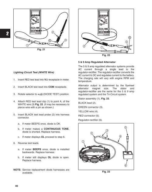
5 & 9 Amp Regulated Alternator<br />
The 5 & 9 amp regulated alternator systems provide<br />
AC current through a single lead to the<br />
regulator-rectifier. The regulator-rectifier converts the<br />
AC current to DC and regulates current to the battery.<br />
The charging rate will vary with engine RPM and<br />
temperature.<br />
Alternator output is determined by the flywheel<br />
alternator magnet size. The stator and<br />
regulator-rectifier are the same for the 5 & 9 amp<br />
regulated system and the Tri-Circuit system.<br />
Stator assembly (1), Fig. 23.<br />
BLACK lead (2).<br />
GREEN connector (3).<br />
YELLOW wire (4).<br />
RED connector (5).<br />
Regulator-rectifier (6).<br />
<br />
<br />
<br />
<br />
<br />
a. If meter BEEPS once, diode is installed<br />
backwards. Replace harness.<br />
b. If meter still displays OL diode is open.<br />
Replace harness.<br />
NOTE: Service replacement diode harnesses are<br />
available.<br />
Fig. 23<br />
<br />
40


