

272144 Vanguard Twin Cylinder OHV BRIGGS & STRATTON.pdf
272144 Vanguard Twin Cylinder OHV BRIGGS & STRATTON.pdf
272144 Vanguard Twin Cylinder OHV BRIGGS & STRATTON.pdf

You also want an ePaper? Increase the reach of your titles
YUMPU automatically turns print PDFs into web optimized ePapers that Google loves.
Diode Test<br />
In the DIODE TEST position, the meter will display<br />
the forward voltage drop across the diode(s). If the<br />
voltage drop is less than 0.7 volts, the meter will<br />
BEEP once and display the voltage drop. A<br />
CONTINUOUS TONE indicates CONTINUITY<br />
(shorted diode) An INCOMPLETE CIRCUIT (open<br />
diode) will be displayed as OL.<br />
1. Insert RED test lead into V receptacle in meter.<br />
2. Insert BLACK test lead into COM receptacle in<br />
meter.<br />
3. Rotate selector to +))))) (DIODE TEST) position.<br />
4. Attach RED test lead clip (1) to point A and<br />
BLACK test lead clip (2) to DC output pin (6),<br />
Fig. 17. (It may be necessary to pierce wire with<br />
a pin as shown.)<br />
a. If meter BEEPS once, diode is OK.<br />
b. If meter makes a CONTINUOUS TONE,<br />
diode is shorted. Replace diode.<br />
c. If meter displays OL, proceed to step 5.<br />
5. Reverse test leads.<br />
a. If meter BEEPS once, diode is installed<br />
backwards. Replace diode.<br />
b. If meter still displays OL, diode is open.<br />
Replace diode.<br />
6. If diode tests OK, check stator for bare wires or<br />
other obvious defects. If grounded leads are not<br />
visible, replace the stator.<br />
NOTE: Service replacement diode harnesses are<br />
available. Use resin core solder when<br />
installing new harness. Use shrink tubing or<br />
tape all connections. DO NOT USE CRIMP<br />
CONNECTORS.<br />
<br />
<br />
A<br />
<br />
<br />
Fig. 17<br />
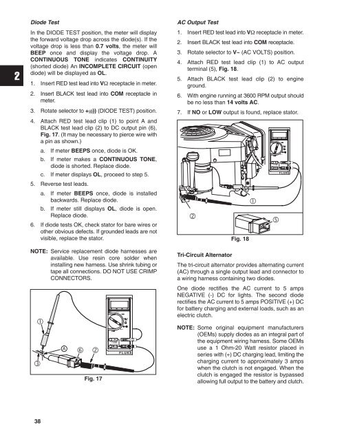
AC Output Test<br />
1. Insert RED test lead into V receptacle in meter.<br />
2. Insert BLACK test lead into COM receptacle.<br />
3. Rotate selector to V~ (AC VOLTS) position.<br />
4. Attach RED test lead clip (1) to AC output<br />
terminal (5), Fig. 18.<br />
5. Attach BLACK test lead clip (2) to engine<br />
ground.<br />
6. With engine running at 3600 RPM output should<br />
be no less than 14 volts AC.<br />
7. If NO or LOW output is found, replace stator.<br />
ÌÌÌ<br />
<br />
Fig. 18<br />
<br />
Ì<br />
<br />
Tri-Circuit Alternator<br />
The tri-circuit alternator provides alternating current<br />
(AC) through a single output lead and connector to<br />
a wiring harness containing two diodes.<br />
One diode rectifies the AC current to 5 amps<br />
NEGATIVE (-) DC for lights. The second diode<br />
rectifies the AC current to 5 amps POSITIVE (+) DC<br />
for battery charging and external loads, such as an<br />
electric clutch.<br />
NOTE: Some original equipment manufacturers<br />
(OEMs) supply diodes as an integral part of<br />
the equipment wiring harness. Some OEMs<br />
use a 1 Ohm-20 Watt resistor placed in<br />
series with (+) DC charging lead, limiting the<br />
charging current to approximately 3 amps<br />
when the clutch is not engaged. When the<br />
clutch is engaged the resistor is bypassed<br />
allowing full output to the battery and clutch.<br />
38


