

272144 Vanguard Twin Cylinder OHV BRIGGS & STRATTON.pdf
272144 Vanguard Twin Cylinder OHV BRIGGS & STRATTON.pdf
272144 Vanguard Twin Cylinder OHV BRIGGS & STRATTON.pdf

Create successful ePaper yourself
Turn your PDF publications into a flip-book with our unique Google optimized e-Paper software.
DC Alternator<br />
The DC alternator provides DC current for charging<br />
a 12 volt battery. The current from the alternator is<br />
unregulated and is rated at 3 amps. The output rises<br />
from 2 amps @ 2400 RPM, to 3 amps @ 3600 RPM.<br />
7. If NO or LOW output is found, test diode.<br />
<br />
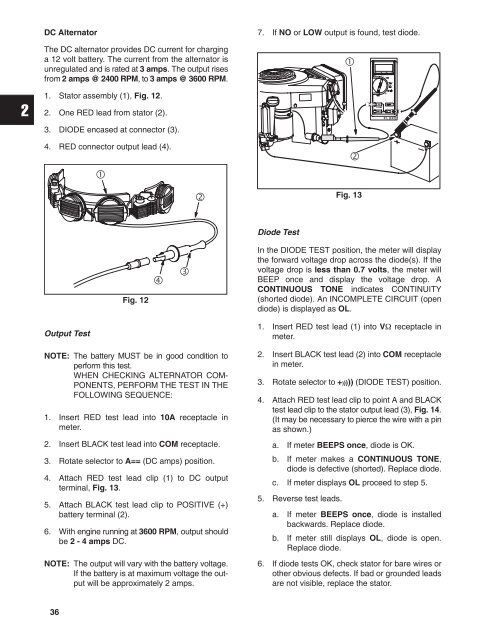
1. Stator assembly (1), Fig. 12.<br />
2. One RED lead from stator (2).<br />
ÌÌ<br />
ÌÌ<br />
Ì<br />
3. DIODE encased at connector (3).<br />
4. RED connector output lead (4).<br />
<br />
<br />
<br />
Fig. 13<br />
Diode Test<br />
Fig. 12<br />
<br />
<br />
In the DIODE TEST position, the meter will display<br />
the forward voltage drop across the diode(s). If the<br />
voltage drop is less than 0.7 volts, the meter will<br />
BEEP once and display the voltage drop. A<br />
CONTINUOUS TONE indicates CONTINUITY<br />
(shorted diode). An INCOMPLETE CIRCUIT (open<br />
diode) is displayed as OL.<br />
Output Test<br />
NOTE: The battery MUST be in good condition to<br />
perform this test.<br />
WHEN CHECKING ALTERNATOR COM-<br />
PONENTS, PERFORM THE TEST IN THE<br />
FOLLOWING SEQUENCE:<br />
1. Insert RED test lead into 10A receptacle in<br />
meter.<br />
2. Insert BLACK test lead into COM receptacle.<br />
3. Rotate selector to A== (DC amps) position.<br />
4. Attach RED test lead clip (1) to DC output<br />
terminal, Fig. 13.<br />
5. Attach BLACK test lead clip to POSITIVE (+)<br />
battery terminal (2).<br />
6. With engine running at 3600 RPM, output should<br />
be 2 - 4 amps DC.<br />
NOTE: The output will vary with the battery voltage.<br />
If the battery is at maximum voltage the output<br />
will be approximately 2 amps.<br />
1. Insert RED test lead (1) into V receptacle in<br />
meter.<br />
2. Insert BLACK test lead (2) into COM receptacle<br />
in meter.<br />
3. Rotate selector to +))))) (DIODE TEST) position.<br />
4. Attach RED test lead clip to point A and BLACK<br />
test lead clip to the stator output lead (3), Fig. 14.<br />
(It may be necessary to pierce the wire with a pin<br />
as shown.)<br />
a. If meter BEEPS once, diode is OK.<br />
b. If meter makes a CONTINUOUS TONE,<br />
diode is defective (shorted). Replace diode.<br />
c. If meter displays OL proceed to step 5.<br />
5. Reverse test leads.<br />
a. If meter BEEPS once, diode is installed<br />
backwards. Replace diode.<br />
b. If meter still displays OL, diode is open.<br />
Replace diode.<br />
6. If diode tests OK, check stator for bare wires or<br />
other obvious defects. If bad or grounded leads<br />
are not visible, replace the stator.<br />
36


