
You also want an ePaper? Increase the reach of your titles
YUMPU automatically turns print PDFs into web optimized ePapers that Google loves.
5-4-5 Definition of Direction<br />
In position mode, user can use Pn314 (Position Command Direction Definition) to define motor rotation<br />
direction. The setting is showed as follow:<br />
Parameter<br />
Signal<br />
★Pn314<br />
Name Setting Description<br />
Definition of position<br />
command direction (from<br />
motor load end)<br />
CCW<br />
CW<br />
0 Clockwise (CW)<br />
1 Counter Clockwise (CCW)<br />
Control<br />
Mode<br />
Pi<br />
Pe<br />
New setting will become effective after re-cycling the power.<br />
5-4-6 Gain Adjustment<br />
The table below shows the parameters for adjusting the position loop.<br />
Two position loop gains can be selected from input contact terminals according to table below.<br />
For selection methods refer to section. 5-3-11.<br />
Parameter<br />
Signal<br />
Name Default Unit Setting Range<br />
Control<br />
Mode<br />
Pn310 Position Loop Gain1 40 1/s 1~450 Pe/Pi<br />
Pn311 Position Loop Gain 2 40 1/s 1~450 Pe/Pi<br />
Pn312 Position Feed-Forward Gain 0 % 0~100 Pe/Pi<br />
Cn033 Speed Feed-Forward Smooth Filter 40 Hz 0~1000 Pe/Pi<br />
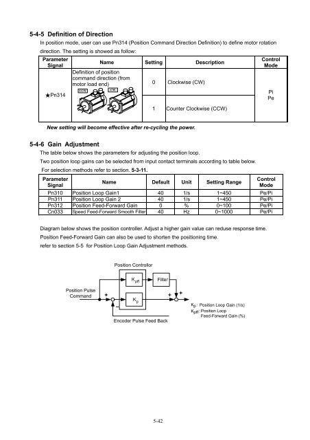
Diagram below shows the position controller. Adjust a higher gain value can reduse response time.<br />
Position Feed-Forward Gain can also be used to shorten the positioning time.<br />
refer to section 5-5 for Position Loop Gain Adjustment methods.<br />
Position Controllor<br />
K pff<br />
Filter<br />
Position Pulse<br />
Command<br />
K p<br />
Encoder Pulse Feed Back<br />
Kp<br />
: Position Loop Gain (1/s)<br />
Kpff<br />
: Position Loop<br />
Feed-Forward Gain (%)<br />
5-42