- Page 2 and 3: ■Warning and Alert: Warning • D
- Page 4 and 5: Contents Chapter 1 Checking and Ins
- Page 6 and 7: 5-6-7 Selecting the External Regene
- Page 8 and 9: 1-1-2 Confirming with Servo Motors
- Page 10 and 11: 1-3 A Brief Introduction of Operati
- Page 12 and 13: 1-4-2 Direction and Distance Fan Fa
- Page 14: 1-5-3 Notice for install motor 1. P
- Page 17 and 18: 2-1-2 Wiring for Servo Drives • T
- Page 19 and 20: 2-1-4 Motor Terminal Layout A Table
- Page 21 and 22: 2-1-5 Typical Wiring for Motor and
- Page 23 and 24: 2-1-7 Wiring for Mechanical Brake R
- Page 25 and 26: 2-2-1 Output Signals from the Servo
- Page 27 and 28: Explanation of General I/O Signal F
- Page 29 and 30: (b) Digital I/O Signal: For many ki
- Page 31 and 32: Digital Input Function Explanation
- Page 33: Digital Output Function Explanation
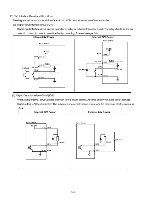
- Page 37 and 38: (f) Analog Output Interface Circuit
- Page 39 and 40: (2) Name and Explanation of I/O Sig
- Page 41 and 42: 2-3-2 Position Control Mode (Pe Mod
- Page 43 and 44: 2-3-4 Speed Control Mode (S Mode) R
- Page 46 and 47: Chapter 3 Panel Operator / Digital
- Page 48 and 49: Once the first parameter in a param
- Page 50 and 51: Step Control Keys LED Display after
- Page 52 and 53: 3-2-2 Diagnostic function Following
- Page 54 and 55: dn-03 (Input terminals status) Use
- Page 56 and 57: dn-07 (Auto offset adjustment of ex
- Page 58: dn-08 Display Motor Standards Cn030
- Page 61 and 62: 4-1 Trial Operation Servo motor wit
- Page 63 and 64: Steps for setting JOG function: Ste
- Page 65 and 66: B. Trial run in Speed control mode(
- Page 67 and 68: C. Position control mode trial run
- Page 70 and 71: Chapter 5 Control Functions 5-1 Con
- Page 72 and 73: 5-2-1 Analog Torque command Ratio.
- Page 74 and 75: 5-2-3 Torque command linear acceler
- Page 76 and 77: 5-2-5 Internal Torque Limit In torq
- Page 78 and 79: 5-3 Speed Mode Speed Mode is necess
- Page 80 and 81: 5-3-2 Analog speed command Ratio An
- Page 82 and 83: Parameter Name Default Unit Setting
- Page 84 and 85:
Setting example: (1) To achieve 95%
- Page 86 and 87:
5-3-7 Setting rotation direction Mo
- Page 88 and 89:
5-3-9 Notch Filter The function of
- Page 90 and 91:
5-3-10 Torque limit of speed contro
- Page 92 and 93:
(1) PI to P mode switch over by com
- Page 94 and 95:
(B) Automatic gain 1& 2 switching S
- Page 96 and 97:
(3) Automatic gain 1&2 switch condi
- Page 98 and 99:
5-3-12 Other Functions When the spe
- Page 100 and 101:
Speed Feed Back Smooth Filter When
- Page 102 and 103:
Two types of pulse command can be c
- Page 104 and 105:
For internal positioning mode there
- Page 106 and 107:
5-4-3 Electronic Gear Electronic ge
- Page 108 and 109:
4.Parameter Setting for Electronic
- Page 110 and 111:
5-4-4 Smooth Acceleration Using the
- Page 112 and 113:
5-4-7 Clear the Pulse Offset In pos
- Page 114 and 115:
Parameter Name Setting Description
- Page 116 and 117:
Home routine Timing Chart During th
- Page 118 and 119:
(2) Pn365.0=1or 3. After starting t
- Page 120 and 121:
(5) Pn365.0=2. After Starting HOME
- Page 122 and 123:
5-4-9 Other Position Function In po
- Page 124 and 125:
Speed Loop Gain Speed Loop Gain has
- Page 126 and 127:
5-5-1 Automatic Adjusting This devi
- Page 128 and 129:
Process for Auto tuning The Diagram
- Page 130 and 131:
5-5-3 Improving Resonance The Servo
- Page 132 and 133:
Parameter Name Description ★Hn502
- Page 134 and 135:
5-6-2 Switch for the Control Mode S
- Page 136 and 137:
Timing for Brake output signal Set
- Page 138 and 139:
5-6-7 Selecting for External Regene
- Page 140 and 141:
Assess for an external resistor and
- Page 142 and 143:
In such applications, calculate ER
- Page 144 and 145:
Chapter 6 Parameter 6-1 Explanation
- Page 146 and 147:
Parameter Name & Function Default U
- Page 148 and 149:
Parameter Name & Function Default U
- Page 150 and 151:
Parameter Name & Function Default U
- Page 152 and 153:
Parameter Name & Function Default U
- Page 154 and 155:
Parameter Name & Function Default U
- Page 156 and 157:
Parameter Name & Function Default U
- Page 158 and 159:
Parameter Sn213 Sn214 Sn215 Speed l
- Page 160 and 161:
Parameter Name & Function Default U
- Page 162 and 163:
Parameter Name & Function Default U
- Page 164 and 165:
Parameter Name & Function Default U
- Page 166 and 167:
Parameter Name & Functions Default
- Page 168 and 169:
Quick Set-up Parameters Parameter N
- Page 170 and 171:
Parameter Signal ★Hn502 ★Hn503
- Page 172 and 173:
Parameter Signal Name & Function De
- Page 174:
Diagnosis Parameter Parameter Name
- Page 178 and 179:
(2) Read consecutive 2 words from d
- Page 180 and 181:
7-1-3 Modbus communication protocol
- Page 182 and 183:
ASCII Mode Framing Symbol Name Desc
- Page 184 and 185:
06H:Write Single Register Write a w
- Page 186 and 187:
10H:Write Multipile Registers Conti
- Page 188 and 189:
CRC Checking: CRC check code is fro
- Page 190 and 191:
Low-Order Byte Table /* Table of CR
- Page 192 and 193:
RS485 RS232 0024 51BH Cn036 Servo I
- Page 194 and 195:
Address RS485 RS232 Parameter Name
- Page 196 and 197:
Display parameters Address RS485 RS
- Page 198 and 199:
Example: Following table are proced
- Page 200 and 201:
Alarm Code Alarm Name and Descripti
- Page 202 and 203:
Alarm Reset Methods 1. carry out th
- Page 204 and 205:
Position Control Mode Command Sourc
- Page 206 and 207:
※ Dimension for TSTA-15 and TSTA-
- Page 208 and 209:
※ Dimension for TSTA-50 and TSTA-
- Page 210 and 211:
TSB 07/08 SERIES SPECIFICATION 1(kg
- Page 212 and 213:
TSB 13 SERIES SPECIFICATION 1(kgf.c
- Page 216 and 217:
Appendix A: Peripheral for Servo mo