
You also want an ePaper? Increase the reach of your titles
YUMPU automatically turns print PDFs into web optimized ePapers that Google loves.
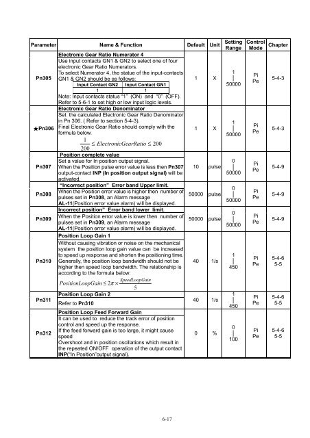
Parameter Name & Function Default Unit<br />
Pn305<br />
★Pn306<br />
Pn307<br />
Pn308<br />
Pn309<br />
Pn310<br />
Pn311<br />
Pn312<br />
Electronic Gear Ratio Numerator 4<br />
Use input contacts GN1 & GN2 to select one of four<br />
electronic Gear Ratio Numerators.<br />
To select Numerator 4, the statue of the input-contacts<br />
GN1 & GN2 should be as follows:<br />
Input Contact GN2 Input Contact GN1<br />
1 1<br />
Note: Input contacts status “1” (ON) and “0” (OFF).<br />
Refer to 5-6-1 to set high or low input logic levels.<br />
Electronic Gear Ratio Denominator<br />
Set the calculated Electronic Gear Ratio Denominator<br />
in Pn 306. ( Refer to section 5-4-3).<br />
Final Electronic Gear Ratio should comply with the<br />
formula below.<br />
1<br />
≤ Electronic GearRatio ≤ 200<br />
200<br />
Position complete value<br />
Set a value for In position output signal.<br />
When the Position pulse error value is less then Pn307<br />
output-contact INP (In position output signal) will be<br />
activated.<br />
“Incorrect position” Error band Upper limit.<br />
When the Position error value is higher then number of<br />
pulses set in Pn308, an Alarm message<br />
AL-11(Position error value alarm) will be displayed.<br />
Incorrect position” Error band lower limit.<br />
When the Position error value is lower then number of<br />
pulses set in Pn309, an Alarm message<br />
AL-11(Position error value alarm) will be displayed.<br />
Position Loop Gain 1<br />
Without causing vibration or noise on the mechanical<br />
system the position loop gain value can be increased<br />
to speed up response and shorten the positioning time.<br />
Generally, the position loop bandwidth should not be<br />
higher then speed loop bandwidth. The relationship is<br />
according to the formula below:<br />
SpeedLoopGain<br />
PositionLo opGain ≤ 2π<br />
×<br />
5<br />
Position Loop Gain 2<br />
Refer to Pn310<br />
Position Loop Feed Forward Gain<br />
It can be used to reduce the track error of position<br />
control and speed up the response.<br />
If the feed forward gain is too large, it might cause<br />
speed<br />
Overshoot and in position oscillations which result in<br />
the repeated ON/OFF operation of the output contact<br />
INP(“In Position”output signal).<br />
1 X<br />
1 X<br />
10 pulse<br />
50000 pulse<br />
50000 pulse<br />
40 1/s<br />
40 1/s<br />
0 %<br />
Setting<br />
Range<br />
1<br />
│<br />
50000<br />
1<br />
│<br />
50000<br />
0<br />
│<br />
50000<br />
0<br />
│<br />
50000<br />
0<br />
│<br />
50000<br />
1<br />
│<br />
450<br />
1<br />
│<br />
450<br />
0<br />
│<br />
100<br />
Control<br />
Mode<br />
Pi<br />
Pe<br />
Pi<br />
Pe<br />
Pi<br />
Pe<br />
Pi<br />
Pe<br />
Pi<br />
Pe<br />
Pi<br />
Pe<br />
Pi<br />
Pe<br />
Pi<br />
Pe<br />
Chapter<br />
5-4-3<br />
5-4-3<br />
5-4-9<br />
5-4-9<br />
5-4-9<br />
5-4-6<br />
5-5<br />
5-4-6<br />
5-5<br />
5-4-6<br />
5-5<br />
6-17