
Create successful ePaper yourself
Turn your PDF publications into a flip-book with our unique Google optimized e-Paper software.
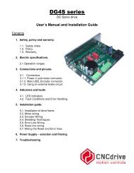
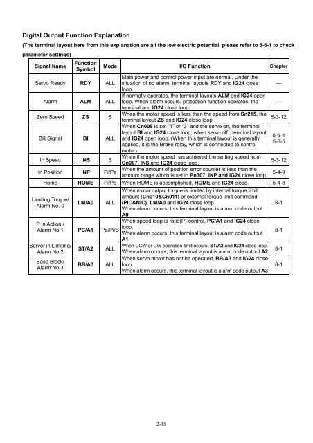
Digital Output Function Explanation<br />
(The terminal layout here from this explanation are all the low electric potential, please refer to 5-6-1 to check<br />
parameter settings)<br />
Signal Name<br />
Function<br />
Symbol<br />
Servo Ready RDY ALL<br />
Alarm ALM ALL<br />
Zero Speed ZS S<br />
BK Signal BI ALL<br />
In Speed INS S<br />
In Position INP Pi/Pe<br />
Mode I/O Function Chapter<br />
Main power and control power input are normal. Under the<br />
situation of no alarm, terminal layouts RDY and IG24 close<br />
loop.<br />
If normally operates, the terminal layouts ALM and IG24 open<br />
loop. When alarm occurs, protection-function operates, the<br />
terminal and IG24 close loop.<br />
When the motor speed is less than the speed from Sn215, the<br />
terminal layout ZS and IG24 close loop.<br />
When Cn008 is set “1” or “3” and the servo on, the terminal<br />
layout BI and IG24 close loop; when servo off , terminal layout<br />
and IG24 open loop. (When this terminal layout is generally<br />
applied, it is the Brake relay, which is connected to control<br />
motor).<br />
When the motor speed has achieved the setting speed from<br />
Cn007, INS and IG24 close loop.<br />
When the amount of position error counter is less than the<br />
amount range which is set in Pn307, INP and IG24 close loop.<br />
―<br />
―<br />
5-3-12<br />
5-6-4<br />
5-6-5<br />
5-3-12<br />
5-4-9<br />
Home HOME Pi/Pe When HOME is accomplished, HOME and IG24 close. 5-4-8<br />
Limiting Torque/<br />
Alarm No. 0<br />
LM/A0<br />
ALL<br />
P in Action /<br />
Alarm No.1 PC/A1 Pe/Pi/S<br />
Server in Limiting/<br />
Alarm No.2<br />
Base Block/<br />
Alarm No.3<br />
ST/A2<br />
BB/A3<br />
ALL<br />
ALL<br />
When motor output torque is limited by internal torque limit<br />
amount (Cn010&Cn011) or external torque limit command<br />
(PIC&NIC). LM/A0 and IG24 close loop.<br />
When alarm occurs, this terminal layout is alarm code output<br />
A0.<br />
When speed loop is ratio(P)-control, PC/A1 and IG24 close<br />
loop.<br />
When alarm occurs, this terminal layout is alarm code output<br />
A1.<br />
When CCW or CW operation-limit occurs, ST/A2 and IG24 close loop.<br />
When alarm occurs, this terminal layout is alarm code output A2<br />
When servo motor has not be operated, BB/A3 and IG24 close<br />
loop.<br />
When alarm occurs, this terminal layout is alarm code output A3<br />
8-1<br />
8-1<br />
8-1<br />
8-1<br />
2-18