


You also want an ePaper? Increase the reach of your titles
YUMPU automatically turns print PDFs into web optimized ePapers that Google loves.
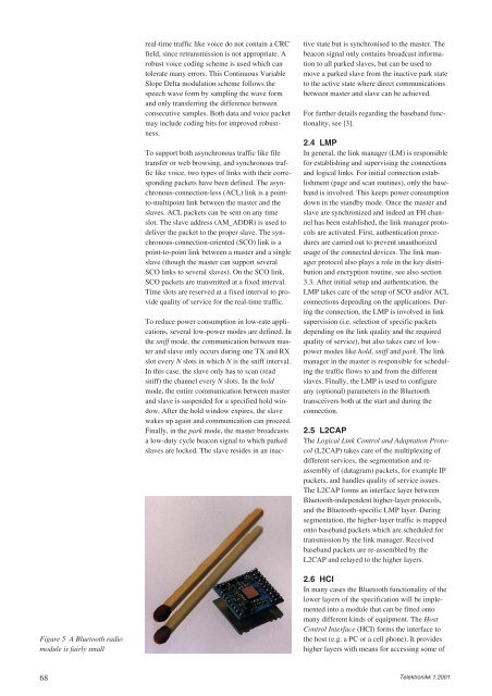
Figure 5 A Bluetooth radio<br />
module is fairly small<br />
68<br />
real-time traffic like voice do not contain a CRC<br />
field, since retransmission is not appropriate. A<br />
robust voice coding scheme is used which can<br />
tolerate many errors. This Continuous Variable<br />
Slope Delta modulation scheme follows the<br />
speech wave form by sampling the wave form<br />
and only transferring the difference between<br />
consecutive samples. Both data and voice packet<br />
may include coding bits for improved robustness.<br />
To support both asynchronous traffic like file<br />
transfer or web browsing, and synchronous traffic<br />
like voice, two types of links with their corresponding<br />
packets have been defined. The asynchronous-connection-less<br />
(ACL) link is a pointto-multipoint<br />
link between the master and the<br />
slaves. ACL packets can be sent on any time<br />
slot. The slave address (AM_ADDR) is used to<br />
deliver the packet to the proper slave. The synchronous-connection-oriented<br />
(SCO) link is a<br />
point-to-point link between a master and a single<br />
slave (though the master can support several<br />
SCO links to several slaves). On the SCO link,<br />
SCO packets are transmitted at a fixed interval.<br />
Time slots are reserved at a fixed interval to provide<br />
quality of service for the real-time traffic.<br />
To reduce power consumption in low-rate applications,<br />
several low-power modes are defined. In<br />
the sniff mode, the communication between master<br />
and slave only occurs during one TX and RX<br />
slot every N slots in which N is the sniff interval.<br />
In this case, the slave only has to scan (read<br />
sniff) the channel every N slots. In the hold<br />
mode, the entire communication between master<br />
and slave is suspended for a specified hold window.<br />
After the hold window expires, the slave<br />
wakes up again and communication can proceed.<br />
Finally, in the park mode, the master broadcasts<br />
a low-duty cycle beacon signal to which parked<br />
slaves are locked. The slave resides in an inac-<br />
tive state but is synchronised to the master. The<br />
beacon signal only contains broadcast information<br />
to all parked slaves, but can be used to<br />
move a parked slave from the inactive park state<br />
to the active state where direct communications<br />
between master and slave can be achieved.<br />
For further details regarding the baseband functionality,<br />
see [3].<br />
2.4 LMP<br />
In general, the link manager (LM) is responsible<br />
for establishing and supervising the connections<br />
and logical links. For initial connection establishment<br />
(page and scan routines), only the baseband<br />
is involved. This keeps power consumption<br />
down in the standby mode. Once the master and<br />
slave are synchronized and indeed an FH channel<br />
has been established, the link manager protocols<br />
are activated. First, authentication procedures<br />
are carried out to prevent unauthorized<br />
usage of the connected devices. The link manager<br />
protocol also plays a role in the key distribution<br />
and encryption routine, see also section<br />
3.3. After initial setup and authentication, the<br />
LMP takes care of the setup of SCO and/or ACL<br />
connections depending on the applications. During<br />
the connection, the LMP is involved in link<br />
supervision (i.e. selection of specific packets<br />
depending on the link quality and the required<br />
quality of service), but also takes care of lowpower<br />
modes like hold, sniff and park. The link<br />
manager in the master is responsible for scheduling<br />
the traffic flows to and from the different<br />
slaves. Finally, the LMP is used to configure<br />
any (optional) parameters in the Bluetooth<br />
transceivers both at the start and during the<br />
connection.<br />
2.5 L2CAP<br />
The Logical Link Control and Adaptation Protocol<br />
(L2CAP) takes care of the multiplexing of<br />
different services, the segmentation and reassembly<br />
of (datagram) packets, for example IP<br />
packets, and handles quality of service issues.<br />
The L2CAP forms an interface layer between<br />
Bluetooth-independent higher-layer protocols,<br />
and the Bluetooth-specific LMP layer. During<br />
segmentation, the higher-layer traffic is mapped<br />
onto baseband packets which are scheduled for<br />
transmission by the link manager. Received<br />
baseband packets are re-assembled by the<br />
L2CAP and relayed to the higher layers.<br />
2.6 HCI<br />
In many cases the Bluetooth functionality of the<br />
lower layers of the specification will be implemented<br />
into a module that can be fitted onto<br />
many different kinds of equipment. The Host<br />
Control Interface (HCI) forms the interface to<br />
the host (e.g. a PC or a cell phone). It provides<br />
higher layers with means for accessing some of<br />
Telektronikk 1.2001


