


You also want an ePaper? Increase the reach of your titles
YUMPU automatically turns print PDFs into web optimized ePapers that Google loves.
exchange is based on the Diffie Hellman procedure.<br />
3 The Radio Resource Control (RRC) is responsible<br />
for the surveillance and efficient use of<br />
available frequency resources. Important functions<br />
of RRC are dynamic frequency selection<br />
(DFS), handover and power control. The DFS<br />
ensures that HIPERLAN/2 will operate in a<br />
plug-and-play manner and frequency planning<br />
will not be required. The decision to initiate a<br />
handover is primarily done by the MT (forced<br />
handover initiated by the AP is also possible)<br />
and three types of handover are supported.<br />
Sector handover if a sector antenna is deployed<br />
(Inter sector/Intra AP), radio handover<br />
if the AP consists of several transceivers<br />
(InterAPT/Intra AP) and network handover<br />
(Inter AP/Intra Network). The network handover<br />
involves higher layers, and signalling via<br />
the backbone may be needed.<br />
3.3 Convergence Layer<br />
The convergence layer acts as a bridge between<br />
higher layer protocols and the DLC Layer. This<br />
involves adapting the service requests from the<br />
higher layers to that used by the DLC layer, and<br />
segmentation/re-assembly of packets to fit the<br />
fixed length of DLC packets. Currently, convergence<br />
layers for ATM, IEEE1394 and Ethernet<br />
have been standardised, and work on a UMTS<br />
CL is underway. The convergence layers can be<br />
split into two different types, cell based (ATM)<br />
[10] and packet based (Ethernet, IEEE1394)<br />
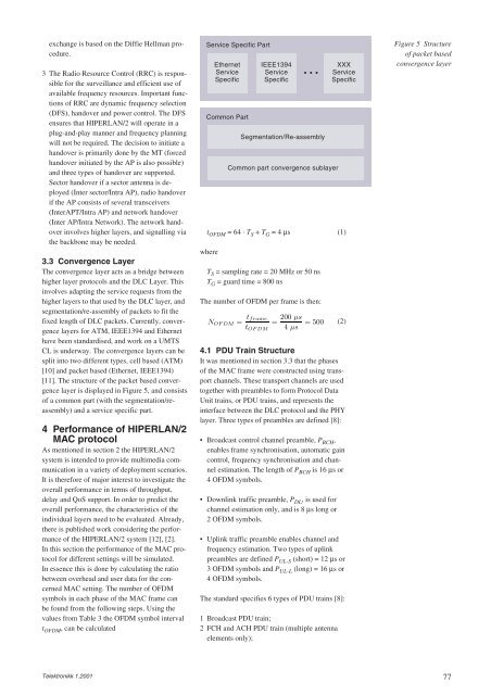
[11]. The structure of the packet based convergence<br />
layer is displayed in Figure 5, and consists<br />
of a common part (with the segmentation/reassembly)<br />
and a service specific part.<br />
4 Performance of HIPERLAN/2<br />
MAC protocol<br />
As mentioned in section 2 the HIPERLAN/2<br />
system is intended to provide multimedia communication<br />
in a variety of deployment scenarios.<br />
It is therefore of major interest to investigate the<br />
overall performance in terms of throughput,<br />
delay and QoS support. In order to predict the<br />
overall performance, the characteristics of the<br />
individual layers need to be evaluated. Already,<br />
there is published work considering the performance<br />
of the HIPERLAN/2 system [12], [2].<br />
In this section the performance of the MAC protocol<br />
for different settings will be simulated.<br />
In essence this is done by calculating the ratio<br />
between overhead and user data for the concerned<br />
MAC setting. The number of OFDM<br />
symbols in each phase of the MAC frame can<br />
be found from the following steps. Using the<br />
values from Table 3 the OFDM symbol interval<br />
t OFDM , can be calculated<br />
Telektronikk 1.2001<br />
Service Specific Part<br />
t OFDM = 64 ⋅ T S + T G = 4 µs (1)<br />
where<br />
Ethernet<br />
Service<br />
Specific<br />
Common Part<br />
IEEE1394<br />
Service<br />
Specific<br />
• • •<br />
Segmentation/Re-assembly<br />
Common part convergence sublayer<br />
T S = sampling rate = 20 MHz or 50 ns<br />
T G = guard time = 800 ns<br />
The number of OFDM per frame is then:<br />
NOFDM = tframe<br />
tOFDM<br />
(2)<br />
4.1 PDU Train Structure<br />
It was mentioned in section 3.3 that the phases<br />
of the MAC frame were constructed using transport<br />
channels. These transport channels are used<br />
together with preambles to form Protocol Data<br />
Unit trains, or PDU trains, and represents the<br />
interface between the DLC protocol and the PHY<br />
layer. Three types of preambles are defined [8]:<br />
• Broadcast control channel preamble, P BCH ,<br />
enables frame synchronisation, automatic gain<br />
control, frequency synchronisation and channel<br />
estimation. The length of P BCH is 16 µs or<br />
4 OFDM symbols.<br />
• Downlink traffic preamble, P DL , is used for<br />
channel estimation only, and is 8 µs long or<br />
2 OFDM symbols.<br />
• Uplink traffic preamble enables channel and<br />
frequency estimation. Two types of uplink<br />
preambles are defined P UL-S (short) = 12 µs or<br />
3 OFDM symbols and P UL-L (long) = 16 µs or<br />
4 OFDM symbols.<br />
The standard specifies 6 types of PDU trains [8]:<br />
1 Broadcast PDU train;<br />
2 FCH and ACH PDU train (multiple antenna<br />
elements only);<br />
= 200 µs<br />
4 µs<br />
= 500<br />
XXX<br />
Service<br />
Specific<br />
Figure 5 Structure<br />
of packet based<br />
convergence layer<br />
77


