


You also want an ePaper? Increase the reach of your titles
YUMPU automatically turns print PDFs into web optimized ePapers that Google loves.
has to pass via the AP, even for communication<br />
between two MTs associated to the AP. It is<br />
assumed that the majority of traffic for the centralised<br />
mode is between entities where only one<br />
is associated to the AP. The other network topology<br />
is called ad-hoc or direct mode, and is used<br />
for communication between two MTs associated<br />
with the same AP. Here, the user data is transmitted<br />
directly between the two MTs and not via<br />
the AP. The control information, however, is<br />
transmitted via the AP, and the AP still controls<br />
the medium access.<br />
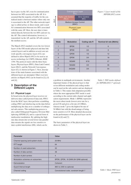
The HiperLAN/2 standard covers the two lowest<br />
layers of the OSI model (physical and data link<br />
control layers) and in addition several core network<br />
specific convergence layers (CL) are<br />
defined to allow HiperLAN/2 to be used as an<br />
access technology for UMTS, Ethernet, IEEE<br />
1394. The protocol stack with the three basic<br />
layers; Physical layer (PHY), Data Link Control<br />
layer (DLC), and the Network Convergence<br />
layer (CL) is shown in Figure 3. Next, descriptions<br />
of the main features associated with the<br />
different layers are attempted. Other overview<br />
articles on HiperLAN/2 can be found in [2], [3]<br />
and [4].<br />
3 Description of the<br />
Different Layers<br />
3.1 Physical Layer<br />
In broad terms the physical layer receives (or<br />
delivers) data (called protocol data unit, PDU)<br />
from the MAC layer, then performs scrambling,<br />
coding (FEC) and interleaving on the data before<br />
multiplexing the data on to a number of orthogonal<br />
sub-carriers. This multiplexing process is<br />
also called Orthogonal Frequency Division Multiplexing<br />
(OFDM) [5], and is a special form of<br />
multicarrier modulation. By splitting the high<br />
rate data stream into several lower rate parallel<br />
data streams the signals are less sensitive to<br />
inter-symbol interference (ISI), which can be<br />
Parameter Value<br />
Channel spacing (and system clock) 20 MHz<br />
FFT length 64<br />
Number of used subcarriers 52<br />
Number of data carriers 48<br />
Number of pilot carriers 4<br />
Telektronikk 1.2001<br />
a problem in multipath environments. Another<br />
important feature of the physical layer is that<br />
seven different modulation and coding modes<br />
can be used on the sub-carriers and are displayed<br />
in Table 2. This makes link adaptation possible<br />
where the most appropriate PHY mode is used<br />
according to the current radio channel and application<br />
requirements. Mode 1 (BPSK) represents<br />
the most robust mode (lowest error rate for a<br />
given C/I) and gives a bit rate of 6 Mbit/s,<br />
whereas mode 7 gives the highest bit rate of<br />
54 Mbit/s but with the disadvantage of being<br />
more sensitive to C/I. More detailed discussions<br />
on the performance of the physical layer can be<br />
found in [6] and [7].<br />
The basic parameters of the physical layer are<br />
shown in Table 3.<br />
Figure 3 Layer model of the<br />
HIPERLAN/2 system<br />
Mode Modulation Coding rate R Nominal bit rate [Mbit/s]<br />
1 BPSK 1/2 6<br />
2 BPSK 3/4 9<br />
3 QPSK 1/2 12<br />
4 QPSK 3/4 18<br />
5 16QAM 9/16 27<br />
6 16QAM 3/4 36<br />
7* 64QAM 3/4 54<br />
Modulation schemes on subcarriers BPSK, QPSK, 16 QAM (64 QAM optional)<br />
DLC<br />
Demodulation Coherent<br />
Radio Link Control<br />
(RLC)<br />
Convergence Layer<br />
(CL)<br />
Error Control<br />
(EC)<br />
Medium Access Control<br />
(MAC)<br />
Physical Layer<br />
(PHY)<br />
Table 2 PHY modes defined<br />
for HIPERLAN/2 (* optional)<br />
Guard Interval length 800 ns (400 ns optional)<br />
Channel coding Convolutional code, constraint length 7 Table 3 Basic PHY layer<br />
parameters<br />
75


