MPLAB ICD 3 In-Circuit Debugger User's Guide
MPLAB ICD 3 In-Circuit Debugger User's Guide
MPLAB ICD 3 In-Circuit Debugger User's Guide
- No tags were found...

You also want an ePaper? Increase the reach of your titles
YUMPU automatically turns print PDFs into web optimized ePapers that Google loves.
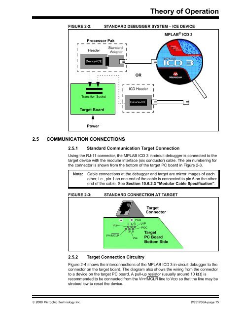
Theory of OperationFIGURE 2-2:STANDARD DEBUGGER SYSTEM – ICE DEVICEProcessor PakHeaderStandardAdapter<strong>MPLAB</strong> ® <strong>ICD</strong> 3Device-ICEOR<strong>ICD</strong> HeaderTransition SocketDevice-ICETarget BoardPower2.5 COMMUNICATION CONNECTIONS2.5.1 Standard Communication Target ConnectionUsing the RJ-11 connector, the <strong>MPLAB</strong> <strong>ICD</strong> 3 in-circuit debugger is connected to thetarget device with the modular interface (six conductor) cable. The pin numbering forthe connector is shown from the bottom of the target PC board in Figure 2-3.Note:Cable connections at the debugger and target are mirror images of eachother, i.e., pin 1 on one end of the cable is connected to pin 6 on the otherend of the cable. See Section 10.6.2.3 “Modular Cable Specification”.FIGURE 2-3:STANDARD CONNECTION AT TARGETTargetConnectorVDDVPP/MCLRPGD2 4 6 LVPPGC1 3 5VssTargetPC BoardBottom Side2.5.2 Target Connection <strong>Circuit</strong>ryFigure 2-4 shows the interconnections of the <strong>MPLAB</strong> <strong>ICD</strong> 3 in-circuit debugger to theconnector on the target board. The diagram also shows the wiring from the connectorto a device on the target PC board. A pull-up resistor (usually around 10 kΩ) isrecommended to be connected from the VPP/MCLR line to VDD so that the line may bestrobed low to reset the device.© 2008 Microchip Technology <strong>In</strong>c. DS51766A-page 15