MPLAB ICD 3 In-Circuit Debugger User's Guide
MPLAB ICD 3 In-Circuit Debugger User's Guide
MPLAB ICD 3 In-Circuit Debugger User's Guide
- No tags were found...

Create successful ePaper yourself
Turn your PDF publications into a flip-book with our unique Google optimized e-Paper software.
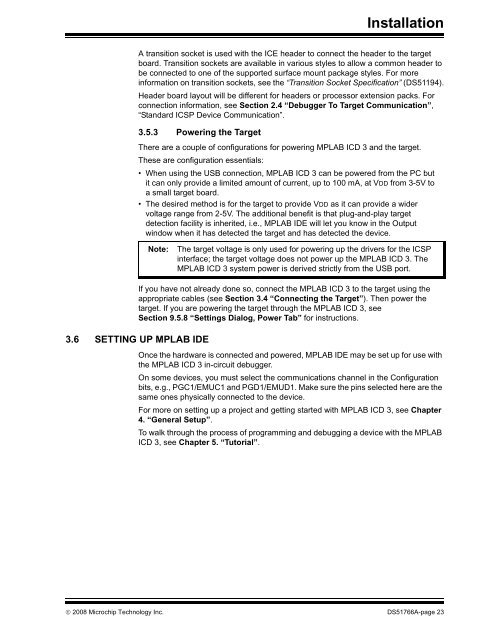
<strong>In</strong>stallationA transition socket is used with the ICE header to connect the header to the targetboard. Transition sockets are available in various styles to allow a common header tobe connected to one of the supported surface mount package styles. For moreinformation on transition sockets, see the “Transition Socket Specification” (DS51194).Header board layout will be different for headers or processor extension packs. Forconnection information, see Section 2.4 “<strong>Debugger</strong> To Target Communication”,“Standard ICSP Device Communication”.3.5.3 Powering the TargetThere are a couple of configurations for powering <strong>MPLAB</strong> <strong>ICD</strong> 3 and the target.These are configuration essentials:• When using the USB connection, <strong>MPLAB</strong> <strong>ICD</strong> 3 can be powered from the PC butit can only provide a limited amount of current, up to 100 mA, at VDD from 3-5V toa small target board.• The desired method is for the target to provide VDD as it can provide a widervoltage range from 2-5V. The additional benefit is that plug-and-play targetdetection facility is inherited, i.e., <strong>MPLAB</strong> IDE will let you know in the Outputwindow when it has detected the target and has detected the device.Note:The target voltage is only used for powering up the drivers for the ICSPinterface; the target voltage does not power up the <strong>MPLAB</strong> <strong>ICD</strong> 3. The<strong>MPLAB</strong> <strong>ICD</strong> 3 system power is derived strictly from the USB port.If you have not already done so, connect the <strong>MPLAB</strong> <strong>ICD</strong> 3 to the target using theappropriate cables (see Section 3.4 “Connecting the Target”). Then power thetarget. If you are powering the target through the <strong>MPLAB</strong> <strong>ICD</strong> 3, seeSection 9.5.8 “Settings Dialog, Power Tab” for instructions.3.6 SETTING UP <strong>MPLAB</strong> IDEOnce the hardware is connected and powered, <strong>MPLAB</strong> IDE may be set up for use withthe <strong>MPLAB</strong> <strong>ICD</strong> 3 in-circuit debugger.On some devices, you must select the communications channel in the Configurationbits, e.g., PGC1/EMUC1 and PGD1/EMUD1. Make sure the pins selected here are thesame ones physically connected to the device.For more on setting up a project and getting started with <strong>MPLAB</strong> <strong>ICD</strong> 3, see Chapter4. “General Setup”.To walk through the process of programming and debugging a device with the <strong>MPLAB</strong><strong>ICD</strong> 3, see Chapter 5. “Tutorial”.© 2008 Microchip Technology <strong>In</strong>c. DS51766A-page 23