MPLAB ICD 3 In-Circuit Debugger User's Guide
MPLAB ICD 3 In-Circuit Debugger User's Guide
MPLAB ICD 3 In-Circuit Debugger User's Guide
- No tags were found...
You also want an ePaper? Increase the reach of your titles
YUMPU automatically turns print PDFs into web optimized ePapers that Google loves.
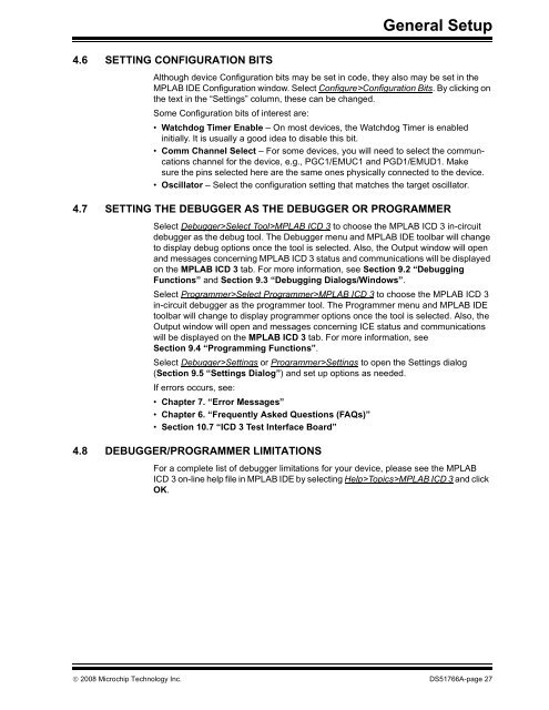
General Setup4.6 SETTING CONFIGURATION BITSAlthough device Configuration bits may be set in code, they also may be set in the<strong>MPLAB</strong> IDE Configuration window. Select Configure>Configuration Bits. By clicking onthe text in the “Settings” column, these can be changed.Some Configuration bits of interest are:• Watchdog Timer Enable – On most devices, the Watchdog Timer is enabledinitially. It is usually a good idea to disable this bit.• Comm Channel Select – For some devices, you will need to select the communcationschannel for the device, e.g., PGC1/EMUC1 and PGD1/EMUD1. Makesure the pins selected here are the same ones physically connected to the device.• Oscillator – Select the configuration setting that matches the target oscillator.4.7 SETTING THE DEBUGGER AS THE DEBUGGER OR PROGRAMMERSelect <strong>Debugger</strong>>Select Tool><strong>MPLAB</strong> <strong>ICD</strong> 3 to choose the <strong>MPLAB</strong> <strong>ICD</strong> 3 in-circuitdebugger as the debug tool. The <strong>Debugger</strong> menu and <strong>MPLAB</strong> IDE toolbar will changeto display debug options once the tool is selected. Also, the Output window will openand messages concerning <strong>MPLAB</strong> <strong>ICD</strong> 3 status and communications will be displayedon the <strong>MPLAB</strong> <strong>ICD</strong> 3 tab. For more information, see Section 9.2 “DebuggingFunctions” and Section 9.3 “Debugging Dialogs/Windows”.Select Programmer>Select Programmer><strong>MPLAB</strong> <strong>ICD</strong> 3 to choose the <strong>MPLAB</strong> <strong>ICD</strong> 3in-circuit debugger as the programmer tool. The Programmer menu and <strong>MPLAB</strong> IDEtoolbar will change to display programmer options once the tool is selected. Also, theOutput window will open and messages concerning ICE status and communicationswill be displayed on the <strong>MPLAB</strong> <strong>ICD</strong> 3 tab. For more information, seeSection 9.4 “Programming Functions”.Select <strong>Debugger</strong>>Settings or Programmer>Settings to open the Settings dialog(Section 9.5 “Settings Dialog”) and set up options as needed.If errors occurs, see:• Chapter 7. “Error Messages”• Chapter 6. “Frequently Asked Questions (FAQs)”• Section 10.7 “<strong>ICD</strong> 3 Test <strong>In</strong>terface Board”4.8 DEBUGGER/PROGRAMMER LIMITATIONSFor a complete list of debugger limitations for your device, please see the <strong>MPLAB</strong><strong>ICD</strong> 3 on-line help file in <strong>MPLAB</strong> IDE by selecting Help>Topics><strong>MPLAB</strong> <strong>ICD</strong> 3 and clickOK.© 2008 Microchip Technology <strong>In</strong>c. DS51766A-page 27


