MPLAB ICD 3 In-Circuit Debugger User's Guide
MPLAB ICD 3 In-Circuit Debugger User's Guide
MPLAB ICD 3 In-Circuit Debugger User's Guide
- No tags were found...

Create successful ePaper yourself
Turn your PDF publications into a flip-book with our unique Google optimized e-Paper software.
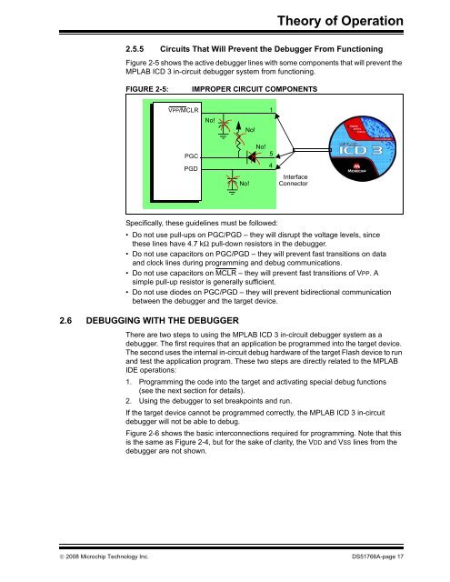
Theory of Operation2.5.5 <strong>Circuit</strong>s That Will Prevent the <strong>Debugger</strong> From FunctioningFigure 2-5 shows the active debugger lines with some components that will prevent the<strong>MPLAB</strong> <strong>ICD</strong> 3 in-circuit debugger system from functioning.FIGURE 2-5:IMPROPER CIRCUIT COMPONENTSVPP/MCLR1No!No!PGCPGDNo!No!54<strong>In</strong>terfaceConnectorSpecifically, these guidelines must be followed:• Do not use pull-ups on PGC/PGD – they will disrupt the voltage levels, sincethese lines have 4.7 kΩ pull-down resistors in the debugger.• Do not use capacitors on PGC/PGD – they will prevent fast transitions on dataand clock lines during programming and debug communications.• Do not use capacitors on MCLR – they will prevent fast transitions of VPP. Asimple pull-up resistor is generally sufficient.• Do not use diodes on PGC/PGD – they will prevent bidirectional communicationbetween the debugger and the target device.2.6 DEBUGGING WITH THE DEBUGGERThere are two steps to using the <strong>MPLAB</strong> <strong>ICD</strong> 3 in-circuit debugger system as adebugger. The first requires that an application be programmed into the target device.The second uses the internal in-circuit debug hardware of the target Flash device to runand test the application program. These two steps are directly related to the <strong>MPLAB</strong>IDE operations:1. Programming the code into the target and activating special debug functions(see the next section for details).2. Using the debugger to set breakpoints and run.If the target device cannot be programmed correctly, the <strong>MPLAB</strong> <strong>ICD</strong> 3 in-circuitdebugger will not be able to debug.Figure 2-6 shows the basic interconnections required for programming. Note that thisis the same as Figure 2-4, but for the sake of clarity, the VDD and VSS lines from thedebugger are not shown.© 2008 Microchip Technology <strong>In</strong>c. DS51766A-page 17