MPLAB ICD 3 In-Circuit Debugger User's Guide
MPLAB ICD 3 In-Circuit Debugger User's Guide
MPLAB ICD 3 In-Circuit Debugger User's Guide
- No tags were found...

You also want an ePaper? Increase the reach of your titles
YUMPU automatically turns print PDFs into web optimized ePapers that Google loves.
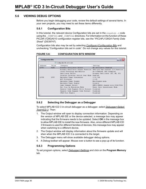
<strong>MPLAB</strong> ® <strong>ICD</strong> 3 <strong>In</strong>-<strong>Circuit</strong> <strong>Debugger</strong> User’s <strong>Guide</strong>5.6 VIEWING DEBUG OPTIONSBefore you begin debugging your code, review the default settings of several items. <strong>In</strong>your own projects, you may need to set these items differently.5.6.1 Configuration Bits<strong>In</strong> this tutorial, the relevant device Configuration bits are set in the counter.c codeusing the _CONFIG1 and _CONFIG2 directives. For information on the function of thesePIC24FJ128GA010 configuration register bits, see the “PIC24FJ128GA Family DataSheet” (DS39747).Configuration bits also may be set by selecting Configure>Configuration Bits andunchecking “Configuration bits set in code”. Do not change any values for this tutorial.FIGURE 5-6:CONFIGURATION BITS WINDOW5.6.2 Selecting the <strong>Debugger</strong> as a <strong>Debugger</strong>To select <strong>MPLAB</strong> <strong>ICD</strong> 3 in-circuit debugger as a debugger, select <strong>Debugger</strong>>SelectTool><strong>ICD</strong> 3. Then:1. The Output window will open to display connection information. Depending onthe version of <strong>MPLAB</strong> IDE or the device selected, a message box may appearindicating that the firmware needs to be updated. Select OK in the message boxto allow <strong>MPLAB</strong> IDE to install the new firmware. Also, since different <strong>MPLAB</strong> <strong>ICD</strong>3 firmware is used for different families of devices, this message box may appearwhen switching to a different device.2. The Output window will display information about the firmware update and willshen when the <strong>MPLAB</strong> <strong>ICD</strong> 3 is connected to the target.3. The <strong>Debugger</strong> menu will show available debugger debug options.4. A Debug toolbar will appear. Mouse over a button to see a pop-up of its function.5.6.3 Programming OptionsTo set program options, select <strong>Debugger</strong>>Settings and click on the Program Memorytab.DS51766A-page 36© 2008 Microchip Technology <strong>In</strong>c.