MPLAB ICD 3 In-Circuit Debugger User's Guide
MPLAB ICD 3 In-Circuit Debugger User's Guide
MPLAB ICD 3 In-Circuit Debugger User's Guide
- No tags were found...

You also want an ePaper? Increase the reach of your titles
YUMPU automatically turns print PDFs into web optimized ePapers that Google loves.
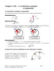
<strong>MPLAB</strong> ® <strong>ICD</strong> 3 <strong>In</strong>-<strong>Circuit</strong> <strong>Debugger</strong> User’s <strong>Guide</strong>FIGURE 2-6:PROPER CONNECTIONS FOR PROGRAMMING+5VProgrammingVoltage<strong>In</strong>ternal <strong>Circuit</strong>s1VDDVPP/MCLR4.7 kΩ5PGC4.7 kΩ4PGDVSSA simplified diagram of some of the internal interface circuitry of the <strong>MPLAB</strong> <strong>ICD</strong> 3in-circuit debugger is shown. For programming, no clock is needed on the targetdevice, but power must be supplied. When programming, the debugger putsprogramming levels on VPP/MCLR, sends clock pulses on PGC and serial data viaPGD. To verify that the part has been programmed correctly, clocks are sent to PGCand data is read back from PGD. This conforms to the ICSP protocol of the deviceunder development.2.7 REQUIREMENTS FOR DEBUGGINGTo debug (set breakpoints, see registers, etc.) with the <strong>MPLAB</strong> <strong>ICD</strong> 3 in-circuitdebugger system, there are critical elements that must be working correctly:• The debugger must be connected to a PC. It must be powered by the PC via theUSB cable, and it must be communicating with the <strong>MPLAB</strong> IDE software via theUSB cable. See Chapter 3. “<strong>In</strong>stallation” for details.• The debugger must be connected as shown to the VPP, PGC and PGD pins of thetarget device with the modular interface cable (or equivalent). VSS and VDD arealso required to be connected between the debugger and target device.• The target device must have power and a functional, running oscillator. If thetarget device does not run, for any reason, the <strong>MPLAB</strong> <strong>ICD</strong> 3 in-circuit debuggercannot debug.• The target device must have its configuration words programmed correctly:- The oscillator Configuration bits should correspond to RC, XT, etc., dependingupon the target design.- For some devices, the Watchdog Timer is enabled by default and needs to bedisabled.- The target device must not have code protection enabled.- The target device must not have table read protection enabled.• LVP should be disabled.Once the above conditions are met, you may proceed to the following:• Sequence of Operations Leading to Debugging• Debugging Details2.7.1 Sequence of Operations Leading to DebuggingGiven that the Requirements For Debugging are met, these actions can be performedwhen the <strong>MPLAB</strong> <strong>ICD</strong> 3 in-circuit debugger is set as the current debugger from the<strong>MPLAB</strong> IDE menu (<strong>Debugger</strong>>Select Tool><strong>MPLAB</strong> <strong>ICD</strong> 3):• The application code is compiled/assembled by selecting Project>BuildDS51766A-page 18© 2008 Microchip Technology <strong>In</strong>c.