MPLAB ICD 3 In-Circuit Debugger User's Guide
MPLAB ICD 3 In-Circuit Debugger User's Guide
MPLAB ICD 3 In-Circuit Debugger User's Guide
- No tags were found...

You also want an ePaper? Increase the reach of your titles
YUMPU automatically turns print PDFs into web optimized ePapers that Google loves.
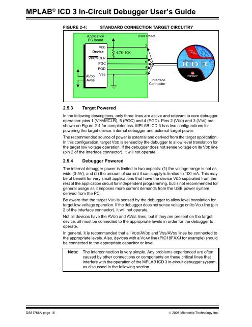
<strong>MPLAB</strong> ® <strong>ICD</strong> 3 <strong>In</strong>-<strong>Circuit</strong> <strong>Debugger</strong> User’s <strong>Guide</strong>FIGURE 2-4:STANDARD CONNECTION TARGET CIRCUITRYApplicationPC BoardVDDDeviceVPP/MCLRPGCPGDVSSAVDDAVSS4.7K-10KUser Reset21543<strong>In</strong>terfaceConnector2.5.3 Target Powered<strong>In</strong> the following descriptions, only three lines are active and relevant to core debuggeroperation: pins 1 (VPP/MCLR), 5 (PGC) and 4 (PGD). Pins 2 (VDD) and 3 (VSS) areshown on Figure 2-4 for completeness. <strong>MPLAB</strong> <strong>ICD</strong> 3 has two configurations forpowering the target device: internal debugger and external target power.The recommended source of power is external and derived from the target application.<strong>In</strong> this configuration, target VDD is sensed by the debugger to allow level translation forthe target low voltage operation. If the debugger does not sense voltage on its VDD line(pin 2 of the interface connector), it will not operate.2.5.4 <strong>Debugger</strong> PoweredThe internal debugger power is limited in two aspects: (1) the voltage range is not aswide (3-5V); and (2) the amount of current it can supply is limited to 100 mA. This maybe of benefit for very small applications that have the device VDD separated from therest of the application circuit for independent programming, but is not recommended forgeneral usage as it imposes more current demands from the USB power systemderived from the PC.Be aware that the target VDD is sensed by the debugger to allow level translation fortarget low-voltage operation. If the debugger does not sense voltage on its VDD line (pin2 of the interface connector), it will not operate.Not all devices have the AVDD and AVSS lines, but if they are present on the targetdevice, all must be connected to the appropriate levels in order for the debugger tooperate.<strong>In</strong> general, it is recommended that all VDD/AVDD and VSS/AVSS lines be connected tothe appropriate levels. Also, devices with a VCAP line (PIC18FXXJ for example) shouldbe connected to the appropriate capacitor or level.Note:The interconnection is very simple. Any problems experienced are oftencaused by other connections or components on these critical lines thatinterfere with the operation of the <strong>MPLAB</strong> <strong>ICD</strong> 3 in-circuit debugger system,as discussed in the following section.DS51766A-page 16© 2008 Microchip Technology <strong>In</strong>c.