MPLAB ICD 3 In-Circuit Debugger User's Guide
MPLAB ICD 3 In-Circuit Debugger User's Guide
MPLAB ICD 3 In-Circuit Debugger User's Guide
- No tags were found...
Create successful ePaper yourself
Turn your PDF publications into a flip-book with our unique Google optimized e-Paper software.
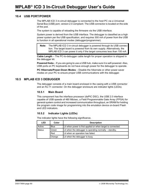
<strong>MPLAB</strong> ® <strong>ICD</strong> 3 <strong>In</strong>-<strong>Circuit</strong> <strong>Debugger</strong> User’s <strong>Guide</strong>10.4 USB PORT/POWERThe <strong>MPLAB</strong> <strong>ICD</strong> 3 in-circuit debugger is connected to the host PC via a UniversalSerial Bus (USB) port, version 2.0 compliant. The USB connector is located on the sideof the pod.The system is capable of reloading the firmware via the USB interface.System power is derived from the USB interface. The debugger is classified as a highpower system per the USB specification, and requires 300 mA of power from the USBto function in all operational modes (debugger/programmer).Note:The <strong>MPLAB</strong> <strong>ICD</strong> 3 in-circuit debugger is powered through its USB connection.The target board is powered from its own supply. Alternatively, the<strong>MPLAB</strong> <strong>ICD</strong> 3 can power it only if the target consumes less than 100 mA.Cable Length – The PC-to-debugger cable length for proper operation is shipped inthe debugger kit.Powered Hubs – If you are going to use a USB hub, make sure it is self-powered. Also,USB ports on PC keyboards do not have enough power for the debugger to operate.PC Hibernate/Power-Down Modes – Disable the hibernate or other power savermodes on your PC to ensure proper USB communications with the debugger.10.5 <strong>MPLAB</strong> <strong>ICD</strong> 3 DEBUGGERThe debugger consists of a main board enclosed in the casing with a USB connectorand an RJ-11 connector. On the debugger enclosure are indicator lights (LEDs).10.5.1 Main BoardThis component has the interface processor (dsPIC DSC), the USB 2.0 interfacecapable of USB speeds of 480 Mb/sec, a Field Programmable Gate Array (FPGA) forgeneral system control and increased communication throughput, an SRAM for holdingthe program code image for programming into the emulation device on-board Flashand LED indicators.10.5.2 <strong>In</strong>dicator Lights (LEDs)The indicator lights have the following significance.LED Color DescriptionActive Blue Lit when power is first applied or when target is connected.Status Green Lit when the debugger is operating normally – standby.Red Lit when an operation has failed.Orange Lit when the debugger is busy.DS51766A-page 80© 2008 Microchip Technology <strong>In</strong>c.


