Model 7002Switch System Instruction Manual - Advanced Test ...
Model 7002Switch System Instruction Manual - Advanced Test ...
Model 7002Switch System Instruction Manual - Advanced Test ...
You also want an ePaper? Increase the reach of your titles
YUMPU automatically turns print PDFs into web optimized ePapers that Google loves.
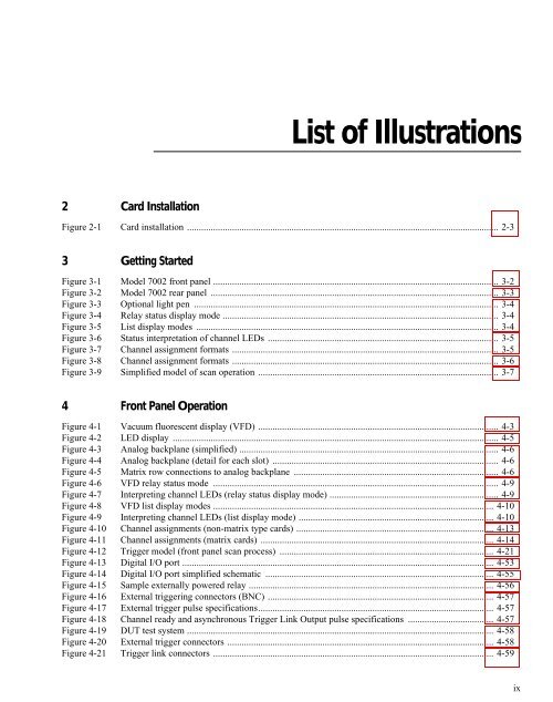
List of Illustrations2 Card InstallationFigure 2-1 Card installation ................................................................................................................................... 2-33 Getting StartedFigure 3-1 <strong>Model</strong> 7002 front panel ........................................................................................................................ 3-2Figure 3-2 <strong>Model</strong> 7002 rear panel ......................................................................................................................... 3-3Figure 3-3 Optional light pen ................................................................................................................................ 3-4Figure 3-4 Relay status display mode .................................................................................................................... 3-4Figure 3-5 List display modes ............................................................................................................................... 3-4Figure 3-6 Status interpretation of channel LEDs ................................................................................................. 3-5Figure 3-7 Channel assignment formats ................................................................................................................ 3-5Figure 3-8 Channel assignment formats ................................................................................................................ 3-6Figure 3-9 Simplified model of scan operation ..................................................................................................... 3-74 Front Panel OperationFigure 4-1 Vacuum fluorescent display (VFD) ..................................................................................................... 4-3Figure 4-2 LED display ......................................................................................................................................... 4-5Figure 4-3 Analog backplane (simplified) ............................................................................................................. 4-6Figure 4-4 Analog backplane (detail for each slot) ............................................................................................... 4-6Figure 4-5 Matrix row connections to analog backplane ...................................................................................... 4-6Figure 4-6 VFD relay status mode ........................................................................................................................ 4-9Figure 4-7 Interpreting channel LEDs (relay status display mode) ....................................................................... 4-9Figure 4-8 VFD list display modes ...................................................................................................................... 4-10Figure 4-9 Interpreting channel LEDs (list display mode) .................................................................................. 4-10Figure 4-10 Channel assignments (non-matrix type cards) ................................................................................... 4-13Figure 4-11 Channel assignments (matrix cards) .................................................................................................. 4-14Figure 4-12 Trigger model (front panel scan process) .......................................................................................... 4-21Figure 4-13 Digital I/O port ................................................................................................................................... 4-53Figure 4-14 Digital I/O port simplified schematic ................................................................................................ 4-55Figure 4-15 Sample externally powered relay ....................................................................................................... 4-56Figure 4-16 External triggering connectors (BNC) ............................................................................................... 4-57Figure 4-17 External trigger pulse specifications................................................................................................... 4-57Figure 4-18 Channel ready and asynchronous Trigger Link Output pulse specifications .................................... 4-57Figure 4-19 DUT test system ................................................................................................................................. 4-58Figure 4-20 External trigger connectors ................................................................................................................ 4-58Figure 4-21 Trigger link connectors ...................................................................................................................... 4-59ix


