- Page 1 and 2: Ofcom Contract AY4620 Assessment of
- Page 3 and 4: 3.4.7 Possible New Technologies (in
- Page 5 and 6: 6.7.4 Regulatory and Standardisatio
- Page 7 and 8: ANNEX 4 List of pertinent ITU Recom
- Page 9 and 10: It is against such socio-economic i
- Page 11 and 12: There appear to be no clear pattern
- Page 13 and 14: General Improvements to the Spectra
- Page 15 and 16: Recommendation 3.22: Ofcom should r
- Page 17 and 18: internationally for decommissioning
- Page 19 and 20: � The study should further ascert
- Page 21 and 22: 2 Introduction to Report In these e
- Page 23 and 24: maritime radiodetermination and rad
- Page 25 and 26: interoperability. These provisions
- Page 27 and 28: • Regulation on the interoperabil
- Page 29 and 30: new entrants and new technologies w
- Page 31 and 32: Foperating MHz B-20dB MHz Foperatin
- Page 33 and 34: Foperating MHz B-20dB MHz Foperatin
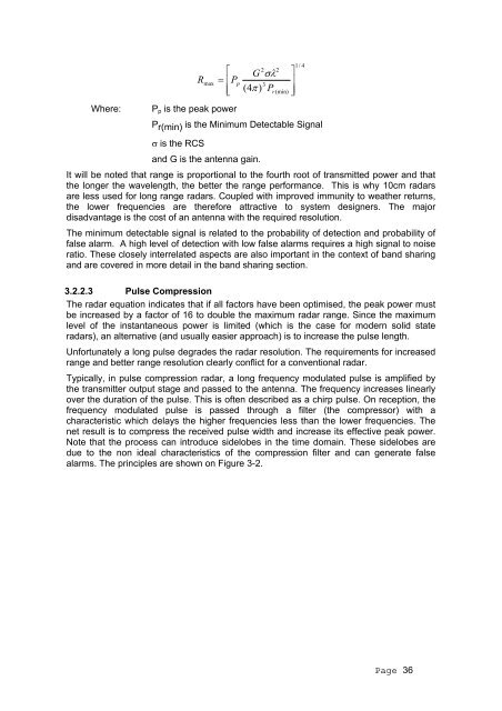
- Page 35: different types of objects (aircraf
- Page 39 and 40: 3.2.2.6 Receivers The receiver syst
- Page 41 and 42: Target size (=Radar Cross Section)
- Page 43 and 44: the normal requirement for 360 degr
- Page 45 and 46: management and planning. They also
- Page 47 and 48: 3.2.5.7 Emission Masks The ITU and
- Page 49 and 50: • A long term policy to replace m
- Page 51 and 52: conditions, the effect of sporadic
- Page 53 and 54: signals which populate the range ce
- Page 55 and 56: potentially suitable band sharing s
- Page 57 and 58: ecommended for future good manageme
- Page 59 and 60: possible options which would reduce
- Page 61 and 62: It should be noted that a number of
- Page 63 and 64: 3.3.3 Technology Description 3.3.3.
- Page 65 and 66: amplitudes of each antenna (calcula
- Page 67 and 68: separation minima to be achieved du
- Page 69 and 70: summary of the most relevant standa
- Page 71 and 72: Co-ordination of PRF (pulse repetit
- Page 73 and 74: Parameter Value Notes Dependencies
- Page 75 and 76: interconnections, plugs, pin layout
- Page 77 and 78: 3.3.8.2 UAT The Universal Access Tr
- Page 79 and 80: Figure 3-12 shows the format and co
- Page 81 and 82: Parameter Value Notes Service topol
- Page 83 and 84: Technology Band/Frequency Informati
- Page 85 and 86: the cost to an already saturated ch
- Page 87 and 88:
3.4.2.5 ILS VOR/ILS localizers are
- Page 89 and 90:
3.4.3 Technology Descriptions EN-RO
- Page 91 and 92:
Figure 3-16 - Current (and future -
- Page 93 and 94:
only a standard omni-directional VH
- Page 95 and 96:
een switched off. L1 and L2 are the
- Page 97 and 98:
landing. He must carry either a rad
- Page 99 and 100:
3.4.4.2 Loran-C Loran-C is promoted
- Page 101 and 102:
Recent studies in the USA have indi
- Page 103 and 104:
Airport GNSS Marker Beacon ILS MLS
- Page 105 and 106:
The demand for the L-Band GNSS freq
- Page 107 and 108:
Airport GNSS Aggregate EPFD limits
- Page 109 and 110:
3.4.6.6 L-Band DME EUROCONTROL’s
- Page 111 and 112:
3.4.8.5 VHF VOR VORs are predominan
- Page 113 and 114:
to aviation. As discussed in sectio
- Page 115 and 116:
3.4.11 Conclusions and Recommendati
- Page 117 and 118:
Table 3-14: Summary of Developments
- Page 119 and 120:
Notes: • The costs are not depend
- Page 121 and 122:
Where technology choices do exist f
- Page 123 and 124:
The implementation of ADS and up an
- Page 125 and 126:
Maritime transport has always been
- Page 127 and 128:
adars operating in their vicinity.
- Page 129 and 130:
are a concern, however for smaller
- Page 131 and 132:
Though the amount of shipping traff
- Page 133 and 134:
4.2.2.5 Possible New Technologies (
- Page 135 and 136:
4.2.3.9 Possible Overall Spectrum E
- Page 137 and 138:
across the complete radar frequency
- Page 139 and 140:
4.3.3.8 Possible Overall Spectrum E
- Page 141 and 142:
educed frequency allocation would t
- Page 143 and 144:
A non harmonised frequency band is
- Page 145 and 146:
5 Aeronautical Communications Civil
- Page 147 and 148:
Within this band, 121.5 MHz and 123
- Page 149 and 150:
5.3.3 Current data link technology
- Page 151 and 152:
absolute priority which is required
- Page 153 and 154:
Note that HF also carries airline o
- Page 155 and 156:
communication services which could,
- Page 157 and 158:
The figure below shows the possible
- Page 159 and 160:
efficient solution (this relates bo
- Page 161 and 162:
5.7.2 VHF Communications Digital Li
- Page 163 and 164:
Parameter Value Notes Channel acces
- Page 165 and 166:
Parameter Value Notes RF Channels M
- Page 167 and 168:
5.8.2.1 Next Generation Satellite S
- Page 169 and 170:
As the new satellite service will s
- Page 171 and 172:
only power limited, and so the rang
- Page 173 and 174:
Parameter Value Notes ATN complianc
- Page 175 and 176:
Figure 5-2: Boeing Connexion system
- Page 177 and 178:
and incur additional aerodynamic dr
- Page 179 and 180:
Encourage move of HF voice to HFDL
- Page 181 and 182:
An illustrative example of airborne
- Page 183 and 184:
Illustrative value of spectrum calc
- Page 185 and 186:
An illustrative calculation of the
- Page 187 and 188:
A VDL2 channel will provide 10 time
- Page 189 and 190:
Recommendation 5.4: The decommissio
- Page 191 and 192:
6 Maritime Communications 6.1 Intro
- Page 193 and 194:
following categories are amongst th
- Page 195 and 196:
navigational information using narr
- Page 197 and 198:
This standard is used around the wo
- Page 199 and 200:
No change in this approach is envis
- Page 201 and 202:
However the situation would be some
- Page 203 and 204:
interest to broadcasters and manufa
- Page 205 and 206:
6.4.1 UK Search and Rescue (SAR) at
- Page 207 and 208:
6.5.1.5 Summary As MF and HF automa
- Page 209 and 210:
• The class of emission, in accor
- Page 211 and 212:
• 415-526.5 kHz (primary or co-pr
- Page 213 and 214:
The United Kingdom has closed down
- Page 215 and 216:
6.6.8 Allocation Sharing issues In
- Page 217 and 218:
in an appropriate manner. Last but
- Page 219 and 220:
automatic facsimile and data system
- Page 221 and 222:
adio-frequency technology with adva
- Page 223 and 224:
6.7.9 Socio-Economic Issues The iss
- Page 225 and 226:
The further development of GSM and
- Page 227 and 228:
or TETRA. Also the integration of G
- Page 229 and 230:
• 161.975 and 162.025 ( formerly
- Page 231 and 232:
Closer to home the CEPT consultativ
- Page 233 and 234:
6.10.3 Operational Requirements The
- Page 235 and 236:
for the purposes of distress and ur
- Page 237 and 238:
million . A digital or dual mode al
- Page 239 and 240:
Inmarsat was the world’s first gl
- Page 241 and 242:
carriage requirements for distress
- Page 243 and 244:
suppliers of radiocommunications eq
- Page 245 and 246:
Authorisations 31 , Article 6 of th
- Page 247 and 248:
Increasing convergence between tele
- Page 249 and 250:
administrations commit themselves t
- Page 251 and 252:
National Regulatory Authority for t
- Page 253 and 254:
7.2.3 Public availability of inform
- Page 255 and 256:
COUNTRY QUESTION 2.1.1 - National O
- Page 257 and 258:
COUNTRY QUESTION 2.1.1 - National O
- Page 259 and 260:
Principal Legal Basis (Primary Legi
- Page 261 and 262:
7.2.5 Change of Control Rules relat
- Page 263 and 264:
FIN Yes Yes No S Yes No No UK No 36
- Page 265 and 266:
Among the specific, identifiable co
- Page 267 and 268:
and charges. The results for those
- Page 269 and 270:
7.2.11 ITU Notification Administrat
- Page 271 and 272:
Frequency Management Costs Y A U No
- Page 273 and 274:
COUNTRY One-Off Administrative Fees
- Page 275 and 276:
Australia Renewal fee £2.69 per as
- Page 277 and 278:
COUNTRY Recurring Administrative Fe
- Page 279 and 280:
COUNTRY Recurring Administrative Fe
- Page 281 and 282:
COUNTRY Recurring Administrative Fe
- Page 283 and 284:
COUNTRY One-Off Spectrum Charges ap
- Page 285 and 286:
COUNTRY Recurring Spectrum Charges
- Page 287 and 288:
COUNTRY Recurring Spectrum Charges
- Page 289 and 290:
limited to vessels registered by th
- Page 291 and 292:
potential band sharing services. Im
- Page 293 and 294:
Very little use is made of the MF t
- Page 295 and 296:
Directive on Marine Equipment, 98/8
- Page 297 and 298:
8.6.4 Other AIP Issues In section 7
- Page 299 and 300:
ASF Additional Secondary Factor ATC
- Page 301 and 302:
ETRA Environment, Transport and Reg
- Page 303 and 304:
MF Medium Frequency (300 kHz - 3000
- Page 305 and 306:
RTCM Radio Technical Commission for
- Page 307 and 308:
ANNEX 2 Mandatory Standards Annex 2
- Page 309 and 310:
Band 328.6-335.4 MHz Service Aerona
- Page 311 and 312:
Band 1559-1626.5 MHz Service Radion
- Page 313 and 314:
Band 5000-5250 MHz Service Aeronaut
- Page 315 and 316:
Band 15.4-15.7 GHz Service Aeronaut
- Page 317 and 318:
Annex 2-2 Maritime Radiodeterminati
- Page 319 and 320:
RTCA MOPS DO 186A - MOPS for airbor
- Page 321 and 322:
Annex 2-4 Maritime Communications S
- Page 323 and 324:
ETSI STANDARDS DESIGNATION ETSI STA
- Page 325 and 326:
Annex 3-2 Maritime Communications E
- Page 327 and 328:
MARITIME SATELLITE EQUIPMENT Networ
- Page 329 and 330:
ANNEX 4 List of pertinent ITU Recom
- Page 331 and 332:
ANNEX 5 Structure of the 4, 6 and 8
- Page 333 and 334:
Sub-band structure of the 8 MHz mar
- Page 335 and 336:
5.2. receive automatically such inf
- Page 337 and 338:
UK Communications Act 2003 (and EC
- Page 339 and 340:
Annex 7-3 Aeronautical Communicatio
- Page 341 and 342:
Summary of the Functional and Techn
- Page 343 and 344:
An economic study to review spectru
- Page 345 and 346:
ANNEX 8 Countries in Receipt of Que