Kleinkrantechnik Small Crane Technology Techique de monorails et ...
Kleinkrantechnik Small Crane Technology Techique de monorails et ...
Kleinkrantechnik Small Crane Technology Techique de monorails et ...

Create successful ePaper yourself
Turn your PDF publications into a flip-book with our unique Google optimized e-Paper software.
30<br />
Montage<br />
Aufhängungen<br />
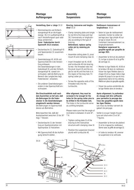
Versteifung, Quer u. Längs 30.10<br />
Klemmenlasche und Einfachstangenkopf<br />
46 an die Kugelstange<br />
39.2 im Laufbahnprofil je<br />
nach Versteifungsart quer o<strong>de</strong>r<br />
längs anklemmen.<br />
Zuvor Fe<strong>de</strong>rstecker durch<br />
Spannstift 39.23 ers<strong>et</strong>zen.<br />
Deckenlasche 31, Gelenkkopf 45<br />
und Spannpratze 32 zusammenbauen.<br />
Gewin<strong>de</strong>stange 40, 40.06 und<br />
Spannschloß 48 in die Versteifung<br />
einbauen.<br />
Die Gewin<strong>de</strong>stangen in <strong>de</strong>n<br />
Gelenkkopf 45 und <strong>de</strong>n Einfachstangenkopf<br />
46 soweit einschrauben,<br />
daß die Bohrung im<br />
Bereich <strong>de</strong>s Langloches liegt.<br />
Fe<strong>de</strong>rstecker eins<strong>et</strong>zen.<br />
Die an<strong>de</strong>ren Gewin<strong>de</strong>stangenen<strong>de</strong>n<br />
in das Spannschloß einschrauben.<br />
Die Einschraubtiefe muß nach<br />
<strong>de</strong>m Ausrichten so tief sein, daß<br />
die Bohrungen für die Fe<strong>de</strong>rstecker<br />
in die Gewin<strong>de</strong>stangen<br />
eingebracht wer<strong>de</strong>n können.<br />
Die Bohrungen im Spannschloß<br />
dienen als Bohrlehre.<br />
Bitte beachten Sie, daß <strong>de</strong>r<br />
Auslenkwinkel zwischen 15 bis 30°<br />
liegt, ↑ Skizzen.<br />
Deckenlasche 31 <strong>de</strong>r Versteifung<br />
an Querkonstruktion mit<br />
Spannpratze 32 festziehen.<br />
Mit Spannschloß 48 die Aufhängung<br />
lotrecht stellen.<br />
30.10<br />
Assembly<br />
Suspensions<br />
Bracing, transverse and longitudinal<br />
30.10<br />
Clamp clamping plate and single<br />
tie rod 46 to the knee-joint bar<br />
39.2 transversely or longitudinally<br />
according to the type of<br />
bracing.<br />
Beforehand, replace spring<br />
cotter pin by r<strong>et</strong>aining pin<br />
39.23.<br />
Assemble ceiling plate 31, pivot<br />
mount 45 and clamping claw 32.<br />
Insert threa<strong>de</strong>d rod 40, 40.06<br />
and turnbuckle 48 into bracing.<br />
Screw the threa<strong>de</strong>d rods into<br />
the pivot mount 45 and the single<br />
tie rod 46 until the hole is in<br />
the region of the long hole. Fit<br />
spring cotter pin.<br />
Screw the opposite ends of the<br />
threa<strong>de</strong>d rods into the<br />
turnbuckle.<br />
After alignment, they must be<br />
screwed in far enough for the<br />
holes for the spring cotter pins to<br />
be drilled in the threa<strong>de</strong>d rods.<br />
The holes in the turnbuckle serve<br />
as a drilling template.<br />
Please make sure that the angle of<br />
inclination is b<strong>et</strong>ween 15 and 30°,<br />
↑ ill.<br />
Tighten ceiling plate 31 of the<br />
bracing to the transverse<br />
structure with clamping claw 32.<br />
Position the suspension brack<strong>et</strong><br />
plumb with turnbuckle 48.<br />
Montage<br />
Suspensions<br />
Raidisseurs transversaux <strong>et</strong><br />
longitudinaux 30.10<br />
Selon le type <strong>de</strong> raidissement<br />
souhaité, monter le collier <strong>de</strong><br />
serrage pour tige simple 46 sur<br />
la tige à rotule 39.2 en<br />
l'orientant transversalement ou<br />
longitudinalement.<br />
Remplacer auparavant la<br />
goupille-agrafe par goupille <strong>de</strong><br />
serrage 3923.<br />
Assembler la ferrure <strong>de</strong> plafond<br />
31, la tige à rotule 45 <strong>et</strong> la griffe<br />
<strong>de</strong> serrage 32.<br />
Monter la tige fil<strong>et</strong>ée 40, 40.06 <strong>et</strong><br />
le ten<strong>de</strong>ur 48 dans le raidisseur.<br />
Visser les tiges fil<strong>et</strong>ées dans la<br />
chape 45 <strong>et</strong> la chape mâle à tige<br />
simple 46 jusqu'à ce que le trou<br />
apparaisse dans le trou oblong.<br />
M<strong>et</strong>tre en place la goupille-agrafe.<br />
Visser les autres extrémités <strong>de</strong><br />
la tige fil<strong>et</strong>ée dans le ten<strong>de</strong>ur.<br />
Après alignement, la profon<strong>de</strong>ur<br />
<strong>de</strong> vissage doit être suffisante<br />
pour perm<strong>et</strong>tre le perçage <strong>de</strong>s<br />
trous <strong>de</strong>s goupilles-agrafe dans<br />
les tiges fil<strong>et</strong>ées.<br />
Les trous du ten<strong>de</strong>ur servent <strong>de</strong><br />
gabarit <strong>de</strong> perçage.<br />
Veiller à ce que l'angle d'ouverture<br />
soit situé entre 15 <strong>et</strong> 30°,<br />
↑ figures.<br />
Assembler la ferrure <strong>de</strong> plafond<br />
31 <strong>et</strong> le crapaud du raidisseur.<br />
Serrer avec la griffe <strong>de</strong> serrage 32.<br />
A l'ai<strong>de</strong> du ten<strong>de</strong>ur 48, amener<br />
la suspension à la verticale.<br />
06.02<br />
bakt03b