Kleinkrantechnik Small Crane Technology Techique de monorails et ...
Kleinkrantechnik Small Crane Technology Techique de monorails et ...
Kleinkrantechnik Small Crane Technology Techique de monorails et ...

You also want an ePaper? Increase the reach of your titles
YUMPU automatically turns print PDFs into web optimized ePapers that Google loves.
86<br />
Montage<br />
Hängekrane<br />
Montage Hängekrane<br />
Montage <strong>de</strong>r Hängekranbahn,<br />
↑ 20-40, <strong>de</strong>r Fahrwerkskombinationen,<br />
↑ 72-78.<br />
Einträger-Hängekrane<br />
Der Zusammenbau wird für die<br />
Ausführung "Stromzuführung<br />
Flachleitungen" beschrieben.<br />
Für die Ausführung "Stromzuführung<br />
Schleifleitungen" ist das<br />
Kapitel "Montage Schleifleitungen"<br />
↑ 62-70 zu beachten.<br />
Kranträgeraufhängung 68 an<br />
<strong>de</strong>n Kranträgeren<strong>de</strong>n 1 einführen<br />
und entsprechend <strong>de</strong>m<br />
Kranspurmittenmaß und <strong>de</strong>n<br />
Überstän<strong>de</strong>n plazieren.<br />
Schrauben 68.03 leicht anziehen.<br />
Die Kugelmuttersicherung<br />
68.07 darf zu Montage und Inspektion<br />
nicht gelöst wer<strong>de</strong>n.<br />
Bei einem Kranträgerstoß bitte<br />
die Stoßbedingungen beachten!<br />
↑ 108, "Sicherheitsvorschriften"<br />
und das "ProduktHandbuch<br />
KT 2000".<br />
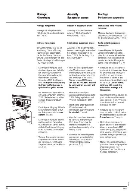
Kranträgeraufhängung 68 in die<br />
Fahrwerkskombination einführen,<br />
Bolzen durchstecken und<br />
sichern, ↑ Skizze.<br />
Kranträgeraufhängung 68 senkrecht<br />
ausrichten. Schrauben<br />
68.03 festziehen. Darauf achten,<br />
daß die Kranträgeraufhängung<br />
in <strong>de</strong>r Aufnahme symm<strong>et</strong>risch<br />
plaziert ist.<br />
Weitere Kranbauteile nach <strong>de</strong>n<br />
folgen<strong>de</strong>n Abschnitten montieren<br />
(siehe auch "Empfohlene<br />
Vorgehensweise bei <strong>de</strong>r Montage",<br />
↑ 18).<br />
Assembly<br />
Suspension cranes<br />
Erection of suspension cranes<br />
Assembly of suspension crane<br />
runway, ↑ 20-40, of travel unit<br />
combinations , ↑ 72-78.<br />
Single gir<strong>de</strong>r suspension cranes<br />
Assembly of the <strong>de</strong>sign "flat cable<br />
festoon power supply" is <strong>de</strong>scribed.<br />
See chapter "Installation of bus<br />
bars", ↑ 62-70, for the <strong>de</strong>sign "bus<br />
bar power supply".<br />
Push the crane gir<strong>de</strong>r suspension<br />
68 with screws loosened<br />
over the crane gir<strong>de</strong>r ends 1 and<br />
position it according to the span<br />
and overhangs of the crane.<br />
Tighten screws 68.03 loosely.<br />
The ball nut lock 68.07 must not<br />
be uncrewed for assembly and<br />
inspection.<br />
Please take note of joint<br />
conditions at crane gir<strong>de</strong>r joints!<br />
↑ 108, "Saf<strong>et</strong>y regulations" and<br />
"Product Handbook KT 2000".<br />
Insert crane gir<strong>de</strong>r suspension<br />
68 into the travel unit<br />
combination, push through and<br />
lock the bolt, ↑ sk<strong>et</strong>ch.<br />
Align the crane beam suspension<br />
68 vertically. Tighten screws<br />
68.03 firmly. Ensure that the<br />
crane beam suspension is<br />
positioned symm<strong>et</strong>rically in the<br />
holding fixture.<br />
Assemble the remaining crane<br />
components according to the<br />
following sections (see also<br />
"Recommen<strong>de</strong>d assembly<br />
procedure", ↑ 18).<br />
Montage<br />
Ponts roulants suspendus<br />
Montage <strong>de</strong>s ponts roulants<br />
suspendus<br />
Montage du chemin <strong>de</strong> roulement<br />
<strong>de</strong>s ponts roulants suspendus ↑ 20-<br />
40, <strong>de</strong>s chariots combinés , ↑ 72-78.<br />
Ponts roulants suspendus<br />
monopoutre<br />
L'assemblage est décrit pour la<br />
version "Alimentation par câbles<br />
plats". Pour la version "Alimentation<br />
par gaines à rails conducteurs", se<br />
reporter au chapitre "Montage <strong>de</strong>s<br />
gaines à rails conducteurs" ↑ 62-70.<br />
Introduire les suspensions du<br />
pont roulant 68 <strong>de</strong>sserrées dans<br />
les extrémités <strong>de</strong>s poutres <strong>de</strong><br />
pont 1 <strong>et</strong> les positionner en<br />
fonction <strong>de</strong> la portée <strong>et</strong> <strong>de</strong>s<br />
porte-à-faux. Serrer légèrement<br />
les vis 68.03. Le frein d'écrou<br />
sphérique 68.7 ne doit être<br />
enlevé ni au montage, ni à<br />
l'inspection.<br />
Pour les jonctions <strong>de</strong> poutres <strong>de</strong><br />
pont, voir les conditions relatives<br />
à ce suj<strong>et</strong>! ↑ 108, "Prescriptions<br />
<strong>de</strong> sécurité" <strong>et</strong> "Manuel<br />
technique KT 2000".<br />
Introduire les suspensions 68<br />
dans le chariot combiné, m<strong>et</strong>tre<br />
en place les axes <strong>de</strong> suspension.<br />
Freiner les axes, ↑ croquis.<br />
M<strong>et</strong>tre les suspensions <strong>de</strong><br />
poutre <strong>de</strong> pont 68 à la verticale.<br />
Visser <strong>et</strong> serrer les vis 68.03.<br />
Veillez à ce que les suspensions<br />
<strong>de</strong> la poutre <strong>de</strong> pont soient positionnées<br />
<strong>de</strong> façon symmétrique<br />
dans les logements.<br />
Monter les autres éléments du<br />
pont dans l'ordre indiqué par les<br />
chapitres suivants (voir<br />
également ↑ 18, "procédure <strong>de</strong><br />
montage conseillée").<br />
06.02<br />
bakt09