Kleinkrantechnik Small Crane Technology Techique de monorails et ...
Kleinkrantechnik Small Crane Technology Techique de monorails et ...
Kleinkrantechnik Small Crane Technology Techique de monorails et ...

Create successful ePaper yourself
Turn your PDF publications into a flip-book with our unique Google optimized e-Paper software.
68<br />
S04 / S44<br />
Montage<br />
Schleifleitungen<br />
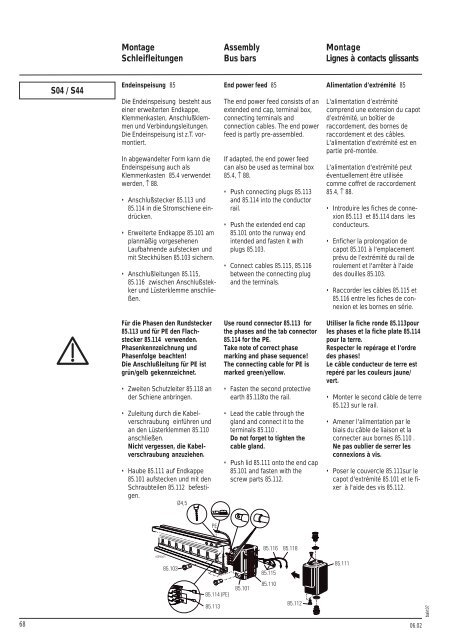
En<strong>de</strong>inspeisung 85<br />
Die En<strong>de</strong>inspeisung besteht aus<br />
einer erweiterten Endkappe,<br />
Klemmenkasten, Anschlußklemmen<br />
und Verbindungsleitungen.<br />
Die En<strong>de</strong>inspeisung ist z.T. vormontiert.<br />
In abgewan<strong>de</strong>lter Form kann die<br />
En<strong>de</strong>inspeisung auch als<br />
Klemmenkasten 85.4 verwen<strong>de</strong>t<br />
wer<strong>de</strong>n, ↑ 88.<br />
Anschlußstecker 85.113 und<br />
85.114 in die Stromschiene eindrücken.<br />
Erweiterte Endkappe 85.101 am<br />
planmäßig vorgesehenen<br />
Laufbahnen<strong>de</strong> aufstecken und<br />
mit Steckhülsen 85.103 sichern.<br />
Anschlußleitungen 85.115,<br />
85.116 zwischen Anschlußstekker<br />
und Lüsterklemme anschließen.<br />
Für die Phasen <strong>de</strong>n Rundstecker<br />
85.113 und für PE <strong>de</strong>n Flachstecker<br />
85.114 verwen<strong>de</strong>n.<br />
Phasenkennzeichnung und<br />
Phasenfolge beachten!<br />
Die Anschlußleitung für PE ist<br />
grün/gelb gekennzeichn<strong>et</strong>.<br />
Zweiten Schutzleiter 85.118 an<br />
<strong>de</strong>r Schiene anbringen.<br />
Zuleitung durch die Kabelverschraubung<br />
einführen und<br />
an <strong>de</strong>n Lüsterklemmen 85.110<br />
anschließen.<br />
Nicht vergessen, die Kabelverschraubung<br />
anzuziehen.<br />
Haube 85.111 auf Endkappe<br />
85.101 aufstecken und mit <strong>de</strong>n<br />
Schraubteilen 85.112 befestigen.<br />
Assembly<br />
Bus bars<br />
End power feed 85<br />
The end power feed consists of an<br />
exten<strong>de</strong>d end cap, terminal box,<br />
connecting terminals and<br />
connection cables. The end power<br />
feed is partly pre-assembled.<br />
If adapted, the end power feed<br />
can also be used as terminal box<br />
85.4, ↑ 88.<br />
Push connecting plugs 85.113<br />
and 85.114 into the conductor<br />
rail.<br />
Push the exten<strong>de</strong>d end cap<br />
85.101 onto the runway end<br />
inten<strong>de</strong>d and fasten it with<br />
plugs 85.103.<br />
Connect cables 85.115, 85.116<br />
b<strong>et</strong>ween the connecting plug<br />
and the terminals.<br />
Use round connector 85.113 for<br />
the phases and the tab connector<br />
85.114 for the PE.<br />
Take note of correct phase<br />
marking and phase sequence!<br />
The connecting cable for PE is<br />
marked green/yellow.<br />
Fasten the second protective<br />
earth 85.118to the rail.<br />
Lead the cable through the<br />
gland and connect it to the<br />
terminals 85.110 .<br />
Do not forg<strong>et</strong> to tighten the<br />
cable gland.<br />
Push lid 85.111 onto the end cap<br />
85.101 and fasten with the<br />
screw parts 85.112.<br />
Montage<br />
Lignes à contacts glissants<br />
Alimentation d'extrémité 85<br />
L'alimentation d’extrémité<br />
comprend une extension du capot<br />
d’extrémité, un boîtier <strong>de</strong><br />
raccor<strong>de</strong>ment, <strong>de</strong>s bornes <strong>de</strong><br />
raccor<strong>de</strong>ment <strong>et</strong> <strong>de</strong>s câbles.<br />
L'alimentation d'extrémité est en<br />
partie pré-montée.<br />
L'alimentation d'extrémité peut<br />
éventuellement être utilisée<br />
comme coffr<strong>et</strong> <strong>de</strong> raccor<strong>de</strong>ment<br />
85.4, ↑ 88.<br />
Introduire les fiches <strong>de</strong> connexion<br />
85.113 <strong>et</strong> 85.114 dans les<br />
conducteurs.<br />
Enficher la prolongation <strong>de</strong><br />
capot 85.101 à l'emplacement<br />
prévu <strong>de</strong> l’extrémité du rail <strong>de</strong><br />
roulement <strong>et</strong> l'arrêter à l'ai<strong>de</strong><br />
<strong>de</strong>s douilles 85.103.<br />
Raccor<strong>de</strong>r les câbles 85.115 <strong>et</strong><br />
85.116 entre les fiches <strong>de</strong> connexion<br />
<strong>et</strong> les bornes en série.<br />
Utiliser la fiche ron<strong>de</strong> 85.113pour<br />
les phases <strong>et</strong> la fiche plate 85.114<br />
pour la terre.<br />
Respecter le repérage <strong>et</strong> l'ordre<br />
<strong>de</strong>s phases!<br />
Le câble conducteur <strong>de</strong> terre est<br />
repéré par les couleurs jaune/<br />
vert.<br />
Monter le second câble <strong>de</strong> terre<br />
85.123 sur le rail.<br />
Amener l'alimentation par le<br />
biais du câble <strong>de</strong> liaison <strong>et</strong> la<br />
connecter aux bornes 85.110 .<br />
Ne pas oublier <strong>de</strong> serrer les<br />
connexions à vis.<br />
Poser le couvercle 85.111sur le<br />
capot d'extrémité 85.101 <strong>et</strong> le fixer<br />
à l'ai<strong>de</strong> <strong>de</strong>s vis 85.112.<br />
06.02<br />
bakt07