buradan - Yangın
buradan - Yangın
buradan - Yangın

You also want an ePaper? Increase the reach of your titles
YUMPU automatically turns print PDFs into web optimized ePapers that Google loves.
TÜYAK BİLDİRİLER KİTABI<br />
2009 PROCEEDINGS BOOK<br />
Modules are supplied pre-assembled and pre mounted and ready<br />
for installation on the ceiling of the tunnel. Each of the modules<br />
includes 10 meter manifold stretch, discharge branch, nozzles and<br />
installation clamps. Primary modules include selector valve with<br />
filter and alarm valve.<br />
For tunnels of up to 10.5 m width one only pipe with nozzles is needed,<br />
with nozzles every 1.0 meters in the middle of the tunnel. In the case<br />
of tunnel of more than 10.5 m additional pipes lines are needed.<br />
Primary modules or activation modules<br />
Figure 2. Activation Module<br />
Primary modules or activation modules are supplied with standard<br />
length of 10 meter. Each one of the modules contains:<br />
w Main stainless steel manifold AISI 316 with unions at each end<br />
PN16. Manifold is supplied with 2 ½”, 3”, 4” or 5” depending on<br />
the hydraulics.<br />
w Discharge branches: stainless steel pipe AISI 316 of 25 mm<br />
diameter.<br />
w Nozzles: Stainless steel nozzles AISI 316 mounted on the<br />
branches. Minimum working pressure 8 bar. Average size of<br />
drops at minimum pressure Dv90% 250 – 350 µm.<br />
w Cut off valve: 1 ½” electrically activated valve.<br />
w Filter: 1 ½” filter with 1 mm mesh.<br />
w Control valve: Selector valve normally closed of 1 ½” electrically<br />
operated with solenoid (12VDC o 24VDC) by means of panel<br />
(included in price).<br />
Secondary modules<br />
Figure 3. Secondary Module<br />
Secondary module is supplied with standard distance of 10 meter.<br />
Each module contains:<br />
w Main manifold: Stainless steel AISI 316 manifold with unions at<br />
each end PN16. Manifold is supplied with diameters of 2 ½”, 3”,<br />
4” o 5” depending on the hydraulics.<br />
w Discharge branch: Stainless steel pipe AISI 316 of 25 mm<br />
diameter.<br />
w Nozzles: Stainless steel nozzles AISI 316 mounted on the<br />
branches. Minimum working pressure 8 bar. Average size of<br />
drops at minimum pressure Dv90% 250 – 350 µm.<br />
4<br />
TÜYAK 2009<br />
Main benefits of this solution compared with high pressure water<br />
mist solutions are:<br />
w Electrical power consumption is lot less than high pressure water<br />
mist solutions. This is a key point in many tunnels since they are<br />
located in remote areas where it’s very costly to provide enough<br />
electricity power to run ventilation and high pressure water mist<br />
solutions.<br />
w Same pump system can be used for hydrants without the need<br />
to provide dedicated pump systems.<br />
And, compared to prescriptive sprinklered solutions (Japanese<br />
regulations):<br />
w Tested with real fire scenarios that represents nowadays reality<br />
in road tunnel. 6 mm/min Japanese Sprinkler design may not be<br />
enough to control and suppress fires. Most tests carried out with<br />
sprinklers were developed on 60’s and 70’s with mainly pool fires<br />
. To the knowledge of the author sprinklers have been tested up<br />
to approximately 25 MW fires.<br />
w Uses 1/3 of the water amount. Consequently protection time<br />
with same water reservoir is multiplied by 3. During Nihonzaka<br />
Tunnel fire incident (11 July 1979) sprinklers managed to control<br />
fire during one hour until reservoir ran dry. After that fire was<br />
uncontrolled and grew dramatically. Fire brigades where unable<br />
to extinguish the fire within that time and fire burned for 7 days.<br />
Additionally this solution offers other advantages:<br />
w Modular and pre assembled solutions easies installation of the<br />
system reducing installation cost and disrupter time of the tunnel<br />
services when installed in already in service tunnels.<br />
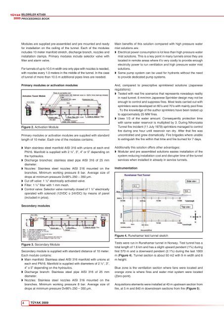
Instrumentation<br />
Figure 4. Runehamar test tunnel sketch<br />
Tests were run in Runehamar tunnel in Norway. Test tunnel has a<br />
total length of 1.6 km and has a slight upward pendent (1%) during<br />
first 570 m and a downward pendent (2.1%) during the last 1000<br />
m (Figure 4). Tunnel section is about 50 m2 with 9 m width and 6<br />
m height.<br />
Blue zone is the ventilation section where fans were located and<br />
orange zone is where fires and water mist system were located<br />
(Zero-point).<br />
Acquisitions elements were installed at 40 m upstream section from<br />
fire, at 5 m and 840 m downstream sections from fire (Figure 5).