- Page 1 and 2: SERVICE MANUAL CONTENTS Parts marke
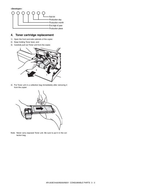
- Page 3 and 4: At the production line, the output
- Page 5 and 6: 8 Power section . . . . . . . . . .
- Page 7 and 8: [2] SPECIFICATIONS 1. Basic Specifi
- Page 9 and 10: 4. GDI printer (AR-203E only) Print
- Page 11: 2. Environmental The environmental
- Page 15 and 16: Power save indicator On: Indicates
- Page 17 and 18: 4. Motors and solenoids 9 No. Part
- Page 19 and 20: 6. PWB unit 9 10 1 4 5 3 7 No. Name
- Page 21 and 22: [5] UNPACKING AND INSTALLATION 1. C
- Page 23 and 24: 9) Shake the aluminum bag to stir d
- Page 25 and 26: B. Installing the software Note: Th
- Page 27 and 28: (2) Using the machine as a shared p
- Page 29 and 30: 11. Interface A. USB Connector Type
- Page 31 and 32: 6) Attach the Scanner motor metal p
- Page 33 and 34: [6] COPY PROCESS 1. Functional diag
- Page 35 and 36: Step-3: Developing (DC bias) A bias
- Page 37 and 38: [7] OPERATIONAL DESCRIPTIONS 1. Out
- Page 39 and 40: 3. Laser unit The image data sent f
- Page 41 and 42: (1) Cassette paper feed operation 1
- Page 43 and 44: (3) Conditions of occurrence of pap
- Page 45 and 46: [8] DISASSEMBLY AND ASSEMBLY Before
- Page 47 and 48: 10) Attach the main charger. Secure
- Page 49 and 50: 2) Remove the screws (4 pcs.), the
- Page 51 and 52: C. Assembly procedure CCD core 1) I
- Page 53 and 54: 10) Remove the spring, and remove t
- Page 55 and 56: 9) Remove each connector and four s
- Page 57 and 58: 21) Remove five screws and the grou
- Page 59 and 60: 31) Remove the screw, slide the lef
- Page 61 and 62: 2) Remove the screw and remove the
- Page 63 and 64:
2) Remove the connector. 3) Remove
- Page 65 and 66:
C. DV blade 1) Peel off the old DV
- Page 67 and 68:
[9] ADJUSTMENTS 1. Optical section
- Page 69 and 70:
(AR-M200/M201) To select the adjust
- Page 71 and 72:
E. Copy density adjustment procedur
- Page 73 and 74:
2) Print start position (Duplex bac
- Page 75 and 76:
Sim No. Sub code Operation 24 15 Sc
- Page 77 and 78:
Main Sub code code 02 02 SPF/RSPF s
- Page 79 and 80:
Main code Sub code Contents Details
- Page 81 and 82:
Main code Sub code Contents Details
- Page 83 and 84:
Main code Sub code Contents Details
- Page 85 and 86:
Main code Sub code Contents Details
- Page 87 and 88:
Main code Sub code Contents Details
- Page 89 and 90:
Main code Sub code Contents Details
- Page 91 and 92:
Main Sub code code 43 04 Fusing tem
- Page 93 and 94:
Main Sub code code 46 12 Density ad
- Page 95 and 96:
Main code Sub code Contents Details
- Page 97 and 98:
Main code Sub code Contents Details
- Page 99 and 100:
Main Sub code code 49 01 Flash ROM
- Page 101 and 102:
Main Sub code code 50 06 Copy lead
- Page 103 and 104:
Main Sub code code 50 19 Duplex cop
- Page 105 and 106:
Main Sub code code 63 02 Black leve
- Page 107 and 108:
Main Sub code code 66 03 FAX PWB me
- Page 109 and 110:
Main Sub code code 66 11 300bps sig
- Page 111 and 112:
Main Sub code code 66 18 DTMF signa
- Page 113 and 114:
Main Sub code code 66 38 Time setti
- Page 115 and 116:
Main Sub code code Details of troub
- Page 117 and 118:
[11] MAINTENANCE 1. Maintenance tab
- Page 119 and 120:
Program No. 25 Copy effective paper
- Page 121 and 122:
Program number 19 AE LEVEL ADJUST 1
- Page 123 and 124:
B. Overall block diagram (AR-M200/M
- Page 125 and 126:
B. MCU PWB (AR-M200/M201) DHAI-0519
- Page 127 and 128:
F. Network box and FAX (AR-M200/M20
- Page 129 and 130:
Signal name Name Function/Operation
- Page 131 and 132:
1 2 3 4 5 MCU PWB (Graphic_ASIC sec
- Page 133 and 134:
1 2 3 4 5 MCU PWB (Driver section 1
- Page 135 and 136:
1 2 3 4 5 MCU PWB (Driver section 3
- Page 137 and 138:
1 2 3 4 5 MCU PWB (Connector sectio
- Page 139 and 140:
1 2 3 4 5 MCU PWB (Scanner I/F sect
- Page 141 and 142:
1 2 3 4 5 MCU PWB (CRUM I/F section
- Page 143 and 144:
E D C B A MCU PWB (ASIC section) (A
- Page 145 and 146:
E D C B A MCU PWB (Memory section)
- Page 147 and 148:
E D C B A MCU PWB (Driver section 2
- Page 149 and 150:
E D C B A MCU PWB (Noise filter/Pul
- Page 151 and 152:
E D C B A MCU PWB (IMC2 USB2.0 sect
- Page 153 and 154:
E D C B A MCU PWB (Connector sectio
- Page 155 and 156:
E D C B A MCU PWB (Scanner I/F sect
- Page 157 and 158:
E D C B A MCU PWB (CRUM I/F section
- Page 159 and 160:
D. OPERATION PWB (AR-M200/M201) E D
- Page 161 and 162:
E D C B A OPERATION PWB (Connector
- Page 163 and 164:
4) PC side: Check that the "Simulat
- Page 165 and 166:
7) PC side: Double-click "Special (
- Page 167 and 168:
5) When the following display is sh
- Page 169 and 170:
8) When the following display is sh
- Page 171 and 172:
5) Select the folder which includes
- Page 173 and 174:
Memo
- Page 175 and 176:
CAUTION FOR BATTERY REPLACEMENT (Da