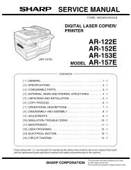
service manual ar-203e ar-203e x ar-m200 ar-m201 model ar-5420
service manual ar-203e ar-203e x ar-m200 ar-m201 model ar-5420
service manual ar-203e ar-203e x ar-m200 ar-m201 model ar-5420

Create successful ePaper yourself
Turn your PDF publications into a flip-book with our unique Google optimized e-Paper software.
[7] OPERATIONAL DESCRIPTIONS<br />
1. Outline of operation<br />
The outline of operation is described referring to the basic configuration.<br />
(Basic configuration)<br />
Operation<br />
section<br />
Printer section<br />
(Outline of copy operation)<br />
CCD<br />
Scanner section<br />
MCU (Main control/image process section)<br />
Laser beam<br />
Process section<br />
LSU (Laser unit)<br />
Laser diode, Polygon mirror lens<br />
Cassette paper<br />
feed section<br />
Paper exit<br />
Setting conditions<br />
1) Set copy conditions such as the copy quantity and the copy<br />
density with the operation section, and press the COPY button.<br />
The information on copy conditions is sent to the MCU.<br />
Image scanning<br />
2) When the COPY button is pressed, the scanner section st<strong>ar</strong>ts<br />
scanning of images.<br />
The light from the copy lamp is reflected by the document and<br />
passed through the lens to the CCD.<br />
Photo signal/Electric signal conversion<br />
3) The image is converted into electrical signals by the CCD circuit<br />
and passed to the MCU.<br />
Image process<br />
4) The document image signal sent from the CCD circuit is processed<br />
under the revised conditions and sent to the LSU<br />
(laser unit) as print data.<br />
Electric signal/Photo signal (laser beam) conversion<br />
5) The LSU emits laser beams according to the print data.<br />
(Electrical signals <strong>ar</strong>e converted into photo signals.)<br />
6) The laser beams <strong>ar</strong>e radiated through the polygon mirror and<br />
v<strong>ar</strong>ious lenses to the OPC drum.<br />
Manual paper<br />
feed section<br />
Fusing section<br />
(Option)<br />
FAX modem<br />
FAX I/F<br />
USB<br />
Printer/<br />
Scanner I/F<br />
Paper transport section<br />
AR-203E/<strong>5420</strong>/M200/M201 OPERATIONAL DESCRIPTIONS 7 - 1<br />
AR-M200/M201<br />
USB<br />
FAX<br />
(Option)<br />
USB<br />
Network<br />
Box<br />
AR-203E/M200/M201<br />
Network<br />
Printing<br />
7) Electrostatic latent images <strong>ar</strong>e formed on the OPC drum<br />
according to the laser beams, and the latent images <strong>ar</strong>e developed<br />
to be visible images (toner images).<br />
8) Meanwhile the paper is fed to the image transfer section in<br />
synchronization with the image lead edge.<br />
9) After the transfer of toner images onto the paper, the toner<br />
images <strong>ar</strong>e fused to the paper by the fusing section. The copied<br />
paper is disch<strong>ar</strong>ged onto the exit tray.<br />
(Outline of printer operation)<br />
The print data sent from the PC <strong>ar</strong>e passed through the NIC PWB<br />
(in case of network connection) and the MCU to the LSU. The procedures<br />
after that <strong>ar</strong>e the same as above 5) and later.<br />
(Outline of scanner operation)<br />
The scan data <strong>ar</strong>e passed through the MCU to the PC according<br />
to the conditions requested by the operations with the operation<br />
panel.<br />
PC