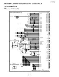
service manual ar-203e ar-203e x ar-m200 ar-m201 model ar-5420
service manual ar-203e ar-203e x ar-m200 ar-m201 model ar-5420
service manual ar-203e ar-203e x ar-m200 ar-m201 model ar-5420

You also want an ePaper? Increase the reach of your titles
YUMPU automatically turns print PDFs into web optimized ePapers that Google loves.
[8] DISASSEMBLY AND ASSEMBLY<br />
Before disassembly, be sure to disconnect the power cord<br />
for safety.<br />
1. Do not disconnect or connect the connector and the<br />
h<strong>ar</strong>ness during the machine is powered. Especially be<br />
c<strong>ar</strong>eful not to disconnect or connect the h<strong>ar</strong>ness<br />
between the MCU PWB and the LSU (MCU PWB: CN119)<br />
during the machine is powered. (If it is disconnected or<br />
connected during the machine is powered, the IC inside<br />
the LSU will be destroyed.)<br />
2. To disconnect the h<strong>ar</strong>ness after turning on the power, be<br />
sure to turn off the power and wait for at least 10 sec<br />
before disconnection. (Note that a voltage still remains<br />
immediately after turning off the power.)<br />
The disassembly and assembly procedures <strong>ar</strong>e described for the<br />
following sections:<br />
1. High voltage section<br />
2. Operation panel section<br />
3. Optical section<br />
4. Fusing section<br />
5. Tray paper feed/transport section<br />
6. Manual paper feed section<br />
7. Re<strong>ar</strong> frame section<br />
8. Power section<br />
9. DV unit section<br />
10. Duplex motor section (AR-M201 only)<br />
11. Reverse roller section (AR-M201 only)<br />
1. High voltage section<br />
A. List<br />
No. P<strong>ar</strong>t name Ref.<br />
1 Drum<br />
2 Transfer ch<strong>ar</strong>ger unit<br />
3 Ch<strong>ar</strong>ger wire<br />
B. Drum replacement<br />
1) Remove the drum cover. (4 Lock Tabs)<br />
AR-203E/<strong>5420</strong>/M200/M201 DISASSEMBLY AND ASSEMBLY 8 - 1<br />
2) Remove the drum fixing plate and the photoconductor drum.<br />
(Note) Dispose the drum fixing plate which was removed.<br />
(2)<br />
LO CK<br />
3) Check the cleaning blade and the red felt for no damage.<br />
If there is any damage, execute all procedures from item 5)<br />
and later.<br />
If there is no damage, execute the procedure of item 12).<br />
4) Remove the main ch<strong>ar</strong>ger.<br />
(When uneven ch<strong>ar</strong>ging occurs, clean the screen grid and the<br />
sawteeth with an air blower.)<br />
5) Remove the cleaning blade.<br />
Note: Dispose the cleaning blade which was removed.<br />
If a cleaning error occurs, replace the cleaning blade.<br />
(Recommendable replacement cycle: Every 25K)<br />
(3)