service manual ar-203e ar-203e x ar-m200 ar-m201 model ar-5420
service manual ar-203e ar-203e x ar-m200 ar-m201 model ar-5420
service manual ar-203e ar-203e x ar-m200 ar-m201 model ar-5420

Create successful ePaper yourself
Turn your PDF publications into a flip-book with our unique Google optimized e-Paper software.
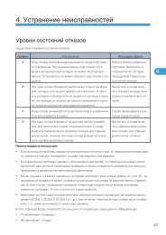
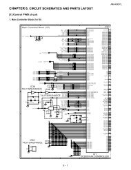
(1) Cassette paper feed operation<br />
1) The figure below shows the positions of the pick-up roller, the<br />
paper feed clutch sleeve, and the paper feed latch in the initial<br />
state without pressing the COPY button after lighting the ready<br />
lamp.<br />
The paper feed latch is in contact with the projection of the<br />
clutch sleeve.<br />
2) When the COPY button is pressed, the main drive motor st<strong>ar</strong>ts<br />
rotating to drive each drive ge<strong>ar</strong>.<br />
The pick-up drive ge<strong>ar</strong> also is driven at that time. Since, however,<br />
the paper feed latch is in contact with the projection of<br />
the clutch sleeve, rotation of the drive ge<strong>ar</strong> is not transmitted to<br />
the pick-up roller, which does not rotate therefore.<br />
PFS<br />
OFF<br />
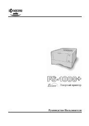
3) After about 0.1 sec from when the main motor st<strong>ar</strong>t rotating,<br />
the tray paper feed solenoid (PFS) turns on for a moment.<br />
This disengages the paper feed latch from the projection of the<br />
clutch sleeve, transmitting rotation of the pick-up drive ge<strong>ar</strong> to<br />
the paper feed roller shaft, rotating the pick-up roller to feed<br />
the paper.<br />
PFS<br />
OFF<br />
RRS<br />
OFF<br />
RRS<br />
OFF<br />
4) After more than half rotation of the pick-up roller, the paper<br />
feed latch is brought in contact with a notch on the clutch<br />
sleeve, stopping rotation of the pick-up roller.<br />
AR-203E/<strong>5420</strong>/M200/M201 OPERATIONAL DESCRIPTIONS 7 - 5<br />
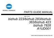
5) At this time, the paper is fed passed the paper entry detection<br />
switch (PPD1), and detected by it. After about 0.15 sec from<br />
detection of paper by PPD1, the tray paper feed solenoid<br />
(PFS) turns on so that the clutch sleeve projection comes into<br />
contact with the paper feed latch to stop the pick-up roller.<br />
Then the pick-up roller rotates for about 0.15 sec so that the<br />
lead edge of the paper is evenly pressed on the resist roller,<br />
preventing against skew feeding.<br />
PFS<br />
ON<br />
6) To release the resist roller, the tray paper feed solenoid and<br />
the resist solenoid <strong>ar</strong>e turned on by the paper st<strong>ar</strong>t signal to<br />
disengage the resist st<strong>ar</strong>t latch from the clutch sleeve, transmitting<br />
rotation of the resist drive ge<strong>ar</strong> to the resist roller shaft.<br />
Thus the paper is transported by the resist roller.<br />
7) After the resist roller st<strong>ar</strong>ts rotating, the paper is passed<br />
through the pre-transfer guide to the transfer section. Images<br />
<strong>ar</strong>e transferred on the paper, which is sep<strong>ar</strong>ated from the OPC<br />
drum by the drum curve and the sep<strong>ar</strong>ation section.<br />
PFS<br />
OFF<br />
RRS<br />
OFF<br />
RRS<br />
ON<br />
8) The paper sep<strong>ar</strong>ated from the drum is passed through the fusing<br />
paper guide, the heat roller (fusing section), POD (paper<br />
out detector) to the copy tray.