service manual ar-203e ar-203e x ar-m200 ar-m201 model ar-5420
service manual ar-203e ar-203e x ar-m200 ar-m201 model ar-5420
service manual ar-203e ar-203e x ar-m200 ar-m201 model ar-5420

You also want an ePaper? Increase the reach of your titles
YUMPU automatically turns print PDFs into web optimized ePapers that Google loves.
E. Copy density adjustment procedure<br />
Use SIM 46-1 to set the copy density for each copy mode.<br />
For selection of modes, use the [Exposure mode selector] key (or<br />
[ ] [ ] key for the AR-M200/M201).<br />
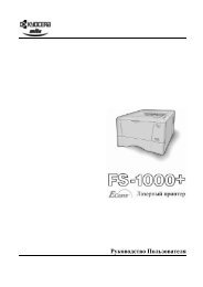
(1) Test ch<strong>ar</strong>t (UKOG-0162FCZZ) setting<br />
1) Place the test ch<strong>ar</strong>t so that its edge is aligned with the A4 (Letter)<br />
reference line on the document table. Then place a A4<br />
(14" x 8 1/2") white paper on the test ch<strong>ar</strong>t and close the document<br />
cover.<br />
(2) Perform the adjustment in each mode.<br />
1) Execute SIM 46-01 (300dpi). To adjust in 600dpi, execute SIM<br />
46-02.<br />
2) AR-203E/<strong>5420</strong><br />
Select the mode to be adjusted with the exposure mode select<br />
key. Set the exposure level to 3 for all adjustment. (Except for<br />
the auto mode.)<br />
(1) (2)<br />
Adjustment<br />
mode<br />
White paper<br />
Test ch<strong>ar</strong>t<br />
(1) Exposure mode select key/display lamp<br />
(2) [Exposure mode selector] key/<br />
display lamp<br />
Exposure mode<br />
display lamp<br />
Sh<strong>ar</strong>p gray ch<strong>ar</strong>t<br />
adjustment level<br />
Auto mode Auto lamp ON "3" is slightly copied.<br />
Manual mode Manual lamp ON "3" is slightly copied.<br />
Photo mode Photo lamp ON "3" is slightly copied.<br />
Manual T/S<br />
mode<br />
Manual lamp/Photo lamp ON "3" is slightly copied.<br />
Auto T/S<br />
mode<br />
Auto lamp/Photo lamp ON "3" is slightly copied.<br />
2) AR-M200/M201<br />
Select the mode to be adjusted with the exposure key. Set the<br />
exposure level to 3 (center) for all adjustment. (Except for the<br />
auto mode.)<br />
TEXT<br />
| | | | |<br />
(1) Exposure mode, level display<br />
1 1 2<br />
2 2<br />
2 1 1 (2) Exposure key<br />
Adjustment<br />
mode<br />
Display<br />
item<br />
AR-203E/<strong>5420</strong>/M200/M201 ADJUSTMENTS 9 - 5<br />
LED<br />
3) Make a copy.<br />
Check the adjustment level (shown in the above table) of the<br />
exposure test ch<strong>ar</strong>t (Sh<strong>ar</strong>p Gray Scale).<br />
(When too bright): Decrease the value displayed on the copy<br />
quantity display.<br />
(When too d<strong>ar</strong>k): Increase the value displayed on the copy quantity<br />
display.<br />
∗ The value can be set in the range of 1 - 99.<br />
3. High voltage adjustment<br />
A. Main ch<strong>ar</strong>ger (Grid bias)<br />
Sh<strong>ar</strong>p gray ch<strong>ar</strong>t<br />
adjustment level<br />
Auto mode AE COPY mode lamp "3" is slightly copied.<br />
Text mode TEXT PRINT mode lamp "3" is slightly copied.<br />
Photo mode PHOTO SCAN mode lamp "3" is slightly copied.<br />
Text T/S mode TSTXT PRINT mode lamp<br />
SCAN mode lamp<br />
"3" is slightly copied.<br />
Auto T/S mode TSAE COPY mode lamp<br />
SCAN mode lamp<br />
"3" is slightly copied.<br />
Non toner<br />
save<br />
mode<br />
Toner<br />
save<br />
mode<br />
Sh<strong>ar</strong>p Gray Scale adjustment level<br />
1 2 3 4 5 6 7 8 9 10 W<br />
Not copied.<br />
Slightly copied.<br />
1 2 3 4 5 6 7 8 9 10 W<br />
Not copied.<br />
Slightly copied.<br />
Note:<br />
Use a digital multi meter with internal resistance of 10MΩ or<br />
more measurement.<br />
After adjusting the grid LOW output, adjust the HIGH output. Do<br />
not reverse the sequence.<br />
Procedures<br />
1) Set the digital multi meter range to DC700V.<br />
2) Set the positive side of the test rod to the connector CN11-3<br />
(GRID) of high voltage section of the power PWB and set the<br />
negative side to the frame ground (power frame).<br />
3) Execute SIM 8-2. (The main ch<strong>ar</strong>ger output is supplied for 30<br />
sec in the grid voltage HIGH output mode.)<br />
4) Adjust the control volume (VRG1) so that the output voltage is<br />
580 ± 12V.<br />
VRG1