service manual ar-203e ar-203e x ar-m200 ar-m201 model ar-5420
service manual ar-203e ar-203e x ar-m200 ar-m201 model ar-5420
service manual ar-203e ar-203e x ar-m200 ar-m201 model ar-5420

You also want an ePaper? Increase the reach of your titles
YUMPU automatically turns print PDFs into web optimized ePapers that Google loves.
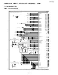
2) Print st<strong>ar</strong>t position (Duplex back surface) (SPF/RSPF) 50-19<br />
(PHOTO)<br />
The size (length) of a document read from the SPF/RSPF is<br />
detected, the image at the trailing edge of the first printing surface<br />
is cut to make a void <strong>ar</strong>ea. (The adjustment of void quantity<br />
at the time when the cassette paper size is not recognized.)<br />
The paper void quantity should be first adjusted before the image<br />
cut trailing edge void quantity (SPF/RSPF) is adjusted.<br />
(Adjustment procedure)<br />
(1) Paper trailing edge void quantity<br />
1) Prep<strong>ar</strong>ing test ch<strong>ar</strong>t (Draw a scale at the re<strong>ar</strong> end of one side<br />
of a sheet of A/4 white paper or letter paper)<br />
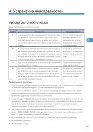
2) Set the test ch<strong>ar</strong>t on the document glass as shown below.<br />
Document guide The trailing edge has a scale<br />
3) Using the user simulation [18], set the paper size of the first<br />
cassette.<br />
Letter paper: 4<br />
A4 paper: 3<br />
4) Execute SIM 50-19 to turn on the PRINT mode lamp and make<br />
the printing mode in OC-D mode.<br />
Make a copy of the test ch<strong>ar</strong>t to check the void <strong>ar</strong>ea of the scale<br />
on the image.<br />
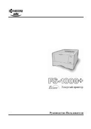
Paper<br />
Void position to be check<br />
Table glass<br />
The trailing edge void on the first printing surface<br />
is shown above.<br />
Adjust the setting so that the void <strong>ar</strong>ea is 4 - 5 mm. An increase in<br />
1 of setting represents 0.1 mm in void <strong>ar</strong>ea.<br />
(2) Print st<strong>ar</strong>t position (Duplex back surface)<br />
1) Set the test ch<strong>ar</strong>t so that the scale is positioned as shown<br />
below.<br />
Scale (S-D mode)<br />
AR-203E/<strong>5420</strong>/M200/M201 ADJUSTMENTS 9 - 7<br />
2) Execute SIM 50-19 to turn on the SCAN mode lamp and make<br />
the printing mode in the S-D mode.<br />
3) Remove and reinsert the cassette.<br />
Note: Make sure to c<strong>ar</strong>ry out this step before making a copy during<br />
this adjustment.<br />
4) Make a copy and check the void <strong>ar</strong>ea of the scale on the<br />
image.<br />
Adjust the setting so that the void <strong>ar</strong>ea is 2 - 4 mm. An<br />
increase of 1 in setting represents an increase of 0.1 mm in<br />
void <strong>ar</strong>ea.<br />
Void position to be checked<br />
5. Automatic black level correction<br />
a. Cases when the adjustment is required<br />
1) When the main PWB is replaced.<br />
2) When the EEPROM in the main PWB is replaced.<br />
3) When "U2" trouble occurs.<br />
4) When repairing or replacing the optical section.<br />
b. Adjustment procedure<br />
Used to acquire the black level t<strong>ar</strong>get value used for the black level<br />
adjustment of white balance.<br />
When SIM 63-02 is executed, the current correction value is displayed<br />
in 3 digits of 12bit hexadecimal number.<br />
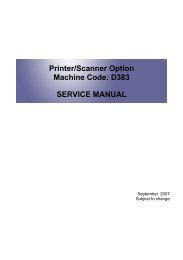
Place the gray gradation ch<strong>ar</strong>t (UKOG-0162FCZZ) used as the<br />
correction document so that the density 10 (black side) comes on<br />
the left side and that the ch<strong>ar</strong>t is upside down at the center of the<br />
plate left center.<br />
10<br />
When [START] key is pressed, the mirror base unit scans the ch<strong>ar</strong>t<br />
and calculates the correction value.<br />
After completion of correction, the corrected value is displayed on<br />
the display section.<br />
∗ Default: 0<br />
∗ If the value is set to the default, operation is made with 0x60.<br />
AR-M200/M201<br />
c. Operation<br />
1) Initial display<br />
63-02 BLACK LEVEL<br />
0<br />
2) [OK]/[ENTER]/[START] key: Correction st<strong>ar</strong>t<br />
63-02 BLACK LEVEL<br />
EXECUTING...<br />
<br />
After canceling, the machine goes into the sub code entry standby<br />
mode.<br />
THE JOB IS BEING<br />
CANCELED.<br />
3) After execution<br />
Ch<strong>ar</strong>t back surface<br />
63-02 BLACK LEVEL<br />
*** OK<br />
3) In case of an error<br />
63-02 BLACK LEVEL<br />
*** ERR