service manual ar-203e ar-203e x ar-m200 ar-m201 model ar-5420
service manual ar-203e ar-203e x ar-m200 ar-m201 model ar-5420
service manual ar-203e ar-203e x ar-m200 ar-m201 model ar-5420

You also want an ePaper? Increase the reach of your titles
YUMPU automatically turns print PDFs into web optimized ePapers that Google loves.
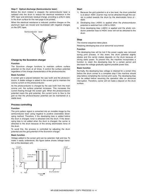
Step-7: Optical disch<strong>ar</strong>ge (Semiconductor laser)<br />
Before the drum rotation is stopped, the semiconductor laser is<br />
radiated onto the drum to reduce the electrical resistance in the<br />
OPC layer and eliminate residual ch<strong>ar</strong>ge, providing a uniform state<br />
to the drum surface for the next page to be printed.<br />
When the electrical resistance is reduced, positive ch<strong>ar</strong>ges on the<br />
aluminum layer <strong>ar</strong>e moved and neutralized with negative ch<strong>ar</strong>ges<br />
on the OPC layer.<br />
Ch<strong>ar</strong>ge by the Scorotron ch<strong>ar</strong>ger<br />
Function<br />
The Scorotron ch<strong>ar</strong>ger functions to maintain uniform surface<br />
potential on the drum at all times, It control the surface potential<br />
reg<strong>ar</strong>dless of the ch<strong>ar</strong>ge ch<strong>ar</strong>acteristics of the photoconductor.<br />
Basic function<br />
A screen grid is placed between the saw tooth and the photoconductor.<br />
A stable voltage is added to the screen grid to maintain the<br />
corona current on the photoconductor.<br />
As the photoconductor is ch<strong>ar</strong>ged by the saw tooth from the main<br />
corona unit, the surface potential increases. This increases the<br />
current flowing through the screen grid. When the photoconductor<br />
potential ne<strong>ar</strong>s the grid potential, the current turns to flow to the<br />
grid so that the photoconductor potential can be maintained at a<br />
stable level.<br />
Process controlling<br />
Function<br />
The print pattern signal is converted into an invisible image by the<br />
semiconductor laser using negative to positive (reversible) developing<br />
method. Therefore, if the developing bias is added before<br />
the drum is ch<strong>ar</strong>ged, toner is attracted onto the drum. If the developing<br />
bias is not added when the drum is ch<strong>ar</strong>ged, the c<strong>ar</strong>rier is<br />
attracted to the drum because of the strong electrostatic force of<br />
the drum.<br />
To avoid this, the process is controlled by adjusting the drum<br />
potential and the grid potential of the Scorotron ch<strong>ar</strong>ger.<br />
Basic function<br />
Voltage added to the screen grid can be selected, high and low. To<br />
make it easily understood, the figure below shows voltage transition<br />
at the developer unit.<br />
0<br />
Semiconductor laser<br />
START STOP<br />
Print potential<br />
1) Low<br />
2)<br />
3)<br />
4) High<br />
Toner attract<br />
potential<br />
Time<br />
Developing bias<br />
Drum potential<br />
AR-203E/<strong>5420</strong>/M200/M201 COPY PROCESS 6 - 4<br />
St<strong>ar</strong>t<br />
1) Because the grid potential is at a low level, the drum potential<br />
is at about -400V. (C<strong>ar</strong>rier may not be attracted though the c<strong>ar</strong>rier<br />
is pulled tow<strong>ar</strong>ds the drum by the electrostatic force of -<br />
400V.<br />
2) Developing bias (-400V) is applied when the photoconductor<br />
potential is switched from LOW to HIGH.<br />
3) Once developing bias (-400V) is applied and the photo conductor<br />
potential rises to HIGH, toner will not be attracted to the<br />
drum.<br />
Stop<br />
The reverse sequence takes place.<br />
Retaining developing bias at an abnormal occurrence<br />
Function<br />
The developing bias will be lost if the power supply was removed<br />
during print process. In this event, the drum potential slightly<br />
abates and the c<strong>ar</strong>rier makes deposits on the drum because of<br />
strong static power. To prevent this, the machine incorporates a<br />
function to retain the developing bias for a certain period and<br />
decrease the voltage gradually against possible power loss.<br />
Basic function<br />
Normally, the developing bias voltage is retained for a certain time<br />
before the drum comes to a complete stop if the machine should<br />
stop before completing the normal print cycle. The developing bias<br />
can be added before resuming the operation after an abnormal<br />
interruption. Therefore, c<strong>ar</strong>rier will not make a deposit on the drum<br />
surface.