service manual ar-203e ar-203e x ar-m200 ar-m201 model ar-5420
service manual ar-203e ar-203e x ar-m200 ar-m201 model ar-5420
service manual ar-203e ar-203e x ar-m200 ar-m201 model ar-5420

Create successful ePaper yourself
Turn your PDF publications into a flip-book with our unique Google optimized e-Paper software.
2. Outline of print process<br />
This printer is a non-impact printer that uses a semiconductor<br />
laser and electrostatic print process. This printer uses an OPC<br />
(Organic Photo Conductor) for its photoconductive material.<br />
First, voltage from the main corona unit ch<strong>ar</strong>ges the drum surface<br />
and a latent image is formed on the drum surface using a laser<br />
beam. This latent image forms a visible image on the drum surface<br />
when toner is applied. The toner image is then transferred onto the<br />
print paper by the transfer corona and fused on the print paper in<br />
the fusing section with a combination of heat and pressure.<br />
Step-1: Ch<strong>ar</strong>ge<br />
Step-2: Exposure<br />
∗ Latent image is formed on the drum.<br />
Step-3: Developing<br />
Latent image formed on the drum is then changed into<br />
visible image with toner.<br />
Step-4: Transfer<br />
The visible image (toner image) on the drum is transferred<br />
onto the print paper.<br />
Step-5: Cleaning<br />
Residual toner on the drum surface is removed and collected<br />
by the cleaning blade.<br />
Step-6: Optical disch<strong>ar</strong>ge<br />
Residual ch<strong>ar</strong>ge on the drum surface is removed, by<br />
semiconductor laser beam.<br />
3. Actual print process<br />
Step-1: DC ch<strong>ar</strong>ge<br />
A uniform negative ch<strong>ar</strong>ge is applied over the OPC drum surface<br />
by the main ch<strong>ar</strong>ging unit. Stable potential is maintained by means<br />
of the Scorotron ch<strong>ar</strong>ger.<br />
Positive ch<strong>ar</strong>ges <strong>ar</strong>e generated in the aluminum layer.<br />
About<br />
DC5.5KV<br />
( 580V/ 400V)<br />
AR-203E/<strong>5420</strong>/M200/M201 COPY PROCESS 6 - 2<br />
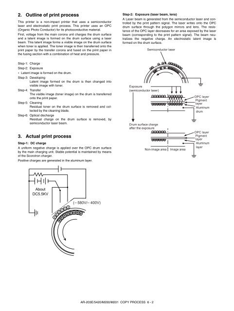
Step-2: Exposure (laser beam, lens)<br />
A Laser beam is generated from the semiconductor laser and controlled<br />
by the print pattern signal. The laser writes onto the OPC<br />
drum surface through the polygon mirrors and lens. The resistance<br />
of the OPC layer decreases for an <strong>ar</strong>ea exposed by the laser<br />
beam (corresponding to the print pattern signal). The beam neutralizes<br />
the negative ch<strong>ar</strong>ge. An electrostatic latent image is<br />
formed on the drum surface.<br />
Exposure<br />
(semiconductor laser)<br />
Drum surface ch<strong>ar</strong>ge<br />
after the exposure<br />
Semiconductor laser<br />
Non-image <strong>ar</strong>ea Image <strong>ar</strong>ea<br />
OPC layer<br />
Pigment<br />
layer<br />
Aluminum<br />
drum<br />
OPC layer<br />
Pigment<br />
layer<br />
Aluminum<br />
layer