

Navy Electricity and Electronics Training Series - Historic Naval ...
Navy Electricity and Electronics Training Series - Historic Naval ...
Navy Electricity and Electronics Training Series - Historic Naval ...

You also want an ePaper? Increase the reach of your titles
YUMPU automatically turns print PDFs into web optimized ePapers that Google loves.
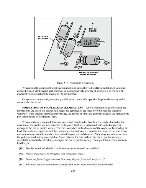
Figure 3-15.—Component arrangement.When possible, component identification markings should be visible after installation. If you mustchoose between identification <strong>and</strong> electrical value markings, the priority of selection is as follows: (1)electrical value, (2) reliability level, <strong>and</strong> (3) part number.Components are normally mounted parallel to <strong>and</strong> on the side opposite the printed circuitry <strong>and</strong> incontact with the board.FORMATION OF PROPER LEAD TERMINATION.—After component leads are formed <strong>and</strong>inserted into the board, the proper lead length <strong>and</strong> termination are made before the lead is soldered.Generally, if the original manufacturer clinched (either full or semi) the component leads, the replacementpart is reinstalled with clinched leads.When clinching is required, leads on single- <strong>and</strong> double-sided boards are securely clinched in thedirection of the printed wiring connected to the pad. Clinching is performed with tools that preventdamage to the pad or printed wiring. The lead is clinched in the direction of the conductor by bending thelead. The leads are clipped so that their minimum clinched length is equal to the radius of the pad. Underno circumstances does the clinched lead extend beyond the pad diameter. Natural springback away fromthe pad or printed wiring is acceptable. A gap between the lead end <strong>and</strong> the pad or printed wiring isacceptable when further clinching endangers the pad or printed wiring. These guidelines ensure uniformlead length.Q14. To what st<strong>and</strong>ards should a technician restore electronic assemblies?Q15. How is oxide removed from pads <strong>and</strong> component leads?Q16. Leads are formed approximately how many degrees from their major axis?Q17. When you replace components, identification marks must meet what requirements?3-22


