those that should be observed when troubleshooting equipment containing semiconductor or other voltage<strong>and</strong> current-sensitive devices.Voltage <strong>and</strong> resistance tests of resistors, transistors, inductors, <strong>and</strong> so forth, are usually effective inlocating complete failures or defects that exhibit large changes from normal circuit characteristics;however, these methods are time-consuming <strong>and</strong> sometimes unsuccessful. The suspect device often mustbe desoldered, removed from the circuit, <strong>and</strong> then retested to verify the fault. If the defect is not verified,the device must be resoldered to the board again. If this procedure has to be repeated several times, or ifthe board is conformally coated, the defect may never be located. In fact, the circuit may be furtherdamaged by the attempt to locate the fault. For these reasons, the device should never be desoldered untilall possible in-circuit tests are performed <strong>and</strong> the defect verified.Q7. List the three groups of test equipment used for fault isolation in 2M repair.Q8. What test equipment continuously monitors electronic systems?Q9. NELAT <strong>and</strong> VAST are examples of what type of test equipment?REPAIR STATIONSIn addition to the requirements for special skills, the repair of 2M electronic circuits also requiresspecial tools. Because these tools are delicate <strong>and</strong> expensive, they are distributed only to trained <strong>and</strong>certified 2M repair technicians.2M repair stations are equipped with electrical <strong>and</strong> mechanical units, tools, <strong>and</strong> general repairmaterials. Such equipments are needed to make reliable repairs to miniature <strong>and</strong> microminiaturecomponent circuit boards.Although most of the tools <strong>and</strong> equipments are common to both miniature <strong>and</strong> microminiature repairstations, several pieces of equipment are used solely with microminiature repair. Precision drill presses<strong>and</strong> stereoscopic-zoom microscopes are examples of microminiature repair equipment normally not foundin a miniature repair station. A brief description of some of the tools <strong>and</strong> equipments <strong>and</strong> their uses willbroaden your knowledge <strong>and</strong> underst<strong>and</strong>ing of 2M repair.The 2M repair set consists of special electrical units, tools, <strong>and</strong> materials necessary to make highreliabilityrepairs to component circuitry. The basic repair set is made up of a repair station power unit,magnifier/light system, card holder, a high-intensity light, a Pana Vise, <strong>and</strong> a tool chest with specializedtools <strong>and</strong> materials. As mentioned previously, stations that have microminiature repair capabilities willinclude a stereoscopic-zoom microscope <strong>and</strong> precision drill press.REPAIR STATION POWER UNITThe repair station power unit is a st<strong>and</strong>ardized system that provides controlled soldering <strong>and</strong>desoldering of all types of solder joint configurations. The unit is shown in figure 2-1. Included in thecontrol unit's capabilities are:2-6
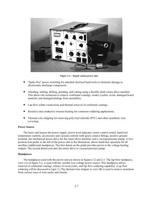
Figure 2-1.—Repair station power unit.• "Spike free" power switching for attached electrical h<strong>and</strong> tools to eliminate damage toelectrostatic discharge components.• Abrading, milling, drilling, grinding, <strong>and</strong> cutting using a flexible shaft, rotary-drive machine.This allows the technician to remove conformal coatings, oxides, eyelets, rivets, damaged boardmaterial, <strong>and</strong> damaged platings from assemblies.• Lap flow solder connections <strong>and</strong> thermal removal of conformal coatings.• Resistive <strong>and</strong> conductive tweezer heating for connector soldering applications.• Thermal wire stripping for removing polyvinyl chloride (PVC) <strong>and</strong> other synethetic wirecoverings.Power SourceThe basic unit houses the power supply, power level indicator, motor control switch, h<strong>and</strong> tooltemperature controls, air pressure <strong>and</strong> vacuum controls with quick connect fittings, positive groundterminal, the mechanical power-drive for the rotary-drive machine, <strong>and</strong> a vacuum/pressure pump. A twopositionfoot pedal, to the left of the power unit in the illustration, allows h<strong>and</strong>-free operation for allancillary (additional) h<strong>and</strong>pieces. The first detent on the pedal provides power to the voltage heatingoutputs. The second detent activates the motor drive or vacuum/pressure pump.H<strong>and</strong>piecesThe h<strong>and</strong>pieces used with the power unit are shown in figures 2-2 <strong>and</strong> 2-3. The lap flow h<strong>and</strong>piece,view (A) of figure 2-2, is used with the variable low-voltage power source. This h<strong>and</strong>piece allowsremoval of conformal coatings, release of sweat joints, <strong>and</strong> lap flow soldering capability. (Lap flowsoldering will be discussed in topic 3.) The thermal wire stripper in view (B) is used to remove insulationfrom various sizes of wire easily <strong>and</strong> cleanly.2-7