The thorny way of truth - Free Energy Community
The thorny way of truth - Free Energy Community
The thorny way of truth - Free Energy Community
- No tags were found...

Create successful ePaper yourself
Turn your PDF publications into a flip-book with our unique Google optimized e-Paper software.
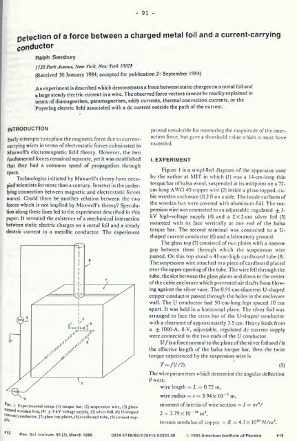
91petection <strong>of</strong> a force between a charged metal foil and a current-carryingconductorRalph Sansbury1120 Park Avenue. New York, New York 10028(Received 30 January 1984; accepted for publication 7 September 1984)An experiment is described which demonstrates a force between static charges on a metal foil anda large steady electric current in a wire. <strong>The</strong> observed force vectors cannot be readily explained interms <strong>of</strong> diamagnetism, paramagnetism, eddy currents, thermal convection currents, or thePoynting electric field associated with a dc current outside the path <strong>of</strong> the current.INTRODUCTIONEarly attempts to explain the magnetic force due to currentcarryingwires in terms <strong>of</strong> electrostatic forces culminated inMaxwell's electromagnetic field theory. However, the tw<strong>of</strong>undamental forces remained separate, yet it was establishedthat they had a common speed <strong>of</strong> propagation throughspace.Technologies initiated by Maxwell's theory have occupiedscientists for more than a century. Interest in the underlyingconnection between magnetic and electrostatic forceswaned. Could there be another relation between the tw<strong>of</strong>orces which is not implied by Maxwell's theory? Speculationalong the.se lines led to the experiment described in thispaper. It revealed the existence <strong>of</strong> a mechanical interactionbetween static electric charges on a metal foil and a steadyelectric current in a metallic conductor. <strong>The</strong> experimentproved unsuitable for measuring the magnitude <strong>of</strong> the interactionforce, but gave a threshold value which it must haveexceeded.1. EXPERIMENTFigure 1 is a simplified diagram <strong>of</strong> the apparatus usedby the author at MIT in which (1) was a 14-cm-long thintorque bar <strong>of</strong> balsa wood, suspended at its midpoint on a 72-cm-long AWG 40 copper wire (2) inside a glass-topped, cubicwooden enclosure (3) 2 ft on a side. <strong>The</strong> inside surfaces <strong>of</strong>the wooden box were covered with aluminum foil. <strong>The</strong> suspensionwire was connected to an adjustable, regulated + 3-kV high-voltage .supply (4) and a 2x2-cm silver foil (5)mounted with its face vertically at one end <strong>of</strong> the balsatorque bar. <strong>The</strong> second terminal was connected to a U-shaped current conductor (6) and a laboratory ground.<strong>The</strong> glass top (7) consisted <strong>of</strong> two plates with a narrowgap between them through which the suspension wirepassed. On this top stood a 41 -cm-high cardboard tube (8).<strong>The</strong> suspension wire attached to a piece <strong>of</strong> cardboard placedover the upper opening <strong>of</strong> the tube. <strong>The</strong> wire fell through thetube, the slot between the glass plates and down to the center<strong>of</strong> the cubic enclosure which prevented air drafts from blowingagainst the silver vane. <strong>The</strong> 0.95-cm-diameter U-shapedcopper conductor passed through the holes in the enclosurewall. <strong>The</strong> U conductor had 50-cm-long legs spaced 10 cmapart. It was held in a horizontal plane. <strong>The</strong> silver foil wasarranged to face the cross bar <strong>of</strong> the U-shaped conductorwith a clearance <strong>of</strong> approximately 3.5 cm. Heavy leads froma + 1000-A, 8-V, adjustable, regulated dc current supplywere connected to the two ends <strong>of</strong> the U conductor.If/is a force normal to the plane <strong>of</strong> the silver foil and /isthe effective length <strong>of</strong> the balsa torque bar, then the twisttorque experienced by the suspension wire isT=f{in].'(1)<strong>The</strong> wire parameters which determine the angular deflection6 were:wire length =L = 0.72 m,wire radius = r = 3.94 X 10~^ m,'O I- Experimental setup: (I) torque bar, (2) suspension wire, (3) glnss-^opped wooden box. (4) + 3-kV voltage supply, (5) silver foil, (6) U-shaped^"ffeni conductor, (7) glass top plates, (8) cardboard tube. (9) current sup-moment <strong>of</strong> inertia <strong>of</strong> wire section = / = irr*/2 = 3.79xlO-"'m\torsion modulus <strong>of</strong> copper = /? = 4.3x 10'" N/m'.