Orion 2117HL High Level Chloride Analyzer User Guide
Orion 2117HL High Level Chloride Analyzer User Guide
Orion 2117HL High Level Chloride Analyzer User Guide

You also want an ePaper? Increase the reach of your titles
YUMPU automatically turns print PDFs into web optimized ePapers that Google loves.
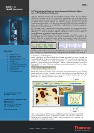
Description of<br />
Basic Controls<br />
Figure III-1<br />
Faceplate<br />
Thermo Scientific <strong>Orion</strong> <strong>2117HL</strong> <strong>High</strong> <strong>Level</strong> <strong>Chloride</strong> <strong>Analyzer</strong> <strong>User</strong> <strong>Guide</strong><br />
Chapter III <strong>Analyzer</strong> Operation<br />
B<br />
E<br />
Ch 1 status Ch 2 status<br />
Parameter Location on Display Options Default<br />
A Mode Indicator Top right corner of display<br />
B<br />
C<br />
D<br />
E<br />
F<br />
HOLD, CAL, SETUP, MEASURE,<br />
DIAGNOSTIC<br />
Marquee Display Top left corner of display <strong>Analyzer</strong> provides prompts for operator<br />
using the scrolling message<br />
t Ch 1<br />
t Ch 2<br />
MEASURE<br />
Temperature Display Celsius In the measure mode, if an ATC probe<br />
is connected the default is the actual<br />
measured temperature and if no ATC<br />
probe is connected the default is 25 °C<br />
Main Data Display Middle line and bottom line of display ISE board: concentration<br />
pH/mV board: pH or mV<br />
Conductivity board: conductivity,<br />
resistivity, salinity, concentration or TDS<br />
Measurement Units<br />
Channel 1 Status<br />
Indicator<br />
Channel 2 Status<br />
Indicator<br />
Left and right side of middle and<br />
bottom display lines<br />
ISE board: ppm or ppb, auto-ranging<br />
pH/mV board: pH or mV<br />
Conductivity board: µS/cm or mS/cm<br />
(conductivity), MΩ-cm (resistivity), SAL1<br />
or SAL2 in the marquee (salinity), PCT1<br />
or PCT2 in the marquee (concentration)<br />
and TDS1 or TDS2 in the marquee (TDS)<br />
Below display screen, to the left of Green LED indicates that channel is OK<br />
Orange LED indicates a channel warning<br />
Red LED indicates a channel failure<br />
Below display screen, to the right of Green LED indicates that channel is OK<br />
Orange LED indicates a channel warning<br />
Red LED indicates a channel failure<br />
D<br />
A<br />
Depends on type of board installed and<br />
selected measurement parameter<br />
Depends on type of board installed and<br />
selected measurement parameter<br />
At initial installation, the red LED<br />
indicates that the electrode or probe<br />
needs to be installed and calibrated.<br />
At initial installation, the red LED<br />
indicates that the electrode or probe<br />
needs to be installed and calibrated.<br />
F<br />
C<br />
III-1