REER-Mosaic Manual
MOSAIC - Installation and use manual
MOSAIC - Installation and use manual

Create successful ePaper yourself
Turn your PDF publications into a flip-book with our unique Google optimized e-Paper software.
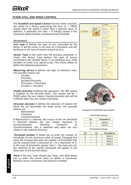
MODULAR SAFETY INTEGRATED CONTROLLER MOSAIC<br />
The<br />
function block monitors<br />
the speed of a device, generating the Zero to 1 (TRUE)<br />
output when the speed is lower than a selected value. In<br />
addition, it generates the Over = 0 (FALSE) output if the<br />
measured speed exceeds a predetermined threshold.<br />
Parameters<br />
It defines the type of axis controlled by the<br />
device. It will be Linear in the case of a translation and will<br />
be Rotary in the case of motion around an axis.<br />
In the event that the previous parameter is<br />
Linear, the Sensor Type defines the type of sensor<br />
connected to the module inputs. It can be Rotary (e.g. shaft<br />
encoder) or Linear (e.g. optical array). This choice allows to<br />
define the following parameters.<br />
It defines the type of sensor(s) used.<br />
The possible choices are:<br />
- Encoder<br />
- Proximity<br />
- Encoder+Proximity<br />
- Proximity1+ Proximity2<br />
- Encoder1+ Encoder2<br />
Enabling this parameter, the DIR output<br />
is enabled on the function block. This output will be 1<br />
(TRUE) when the axis rotates Counterclockwise and will be<br />
0 (FALSE) when the axis rotates Clockwise.<br />
It defines the direction of rotation for<br />
which the set thresholds are made active. The possible<br />
choices are:<br />
- Bidirectional<br />
- Clockwise<br />
- Counterclockwise<br />
If Bidirectional is selected, the excess of the set threshold<br />
is detected whether the axis rotates clockwise or<br />
counterclockwise. Selecting Clockwise or<br />
Counterclockwise, this is detected only when the axis<br />
rotates in the selected direction.<br />
It allows you to enter the number of<br />
thresholds for the maximum value of speed. Changing this<br />
value will increase/decrease the number of thresholds that<br />
can be entered from a minimum of 1 to a maximum of 4.<br />
In the case of thresholds greater than 1, the input pins for<br />
the selection of the specific threshold will appear in the<br />
lower part of the function block.<br />
Example of CLOCKWISE axis rotation<br />
2 threshold settings<br />
In1<br />
Threshold no.<br />
0 Speed 1<br />
1 Speed 2<br />
4 threshold settings<br />
In2 In1 Threshold no.<br />
0 0 Speed 1<br />
0 1 Speed 2<br />
1 0 Speed 3<br />
1 1 Speed 4<br />
English<br />
If the Axis Type chosen was linear, this field allows<br />
you to enter the sensor pitch to obtain a conversion<br />
between sensor revolutions and distance travelled.<br />
106 8540780 • 12/01/2016 • Rev.25


![BRESIMAR(asaTek)-Beckhoff-Livro Formação Técnica TwinCAT 2-v1.2_2009 [pt]](https://img.yumpu.com/62853104/1/190x245/bresimarasatek-beckhoff-livro-formacao-tecnica-twincat-2-v12-2009-pt.jpg?quality=85)